Pantograph monitoring system

A monitoring system and pantograph technology, applied in measurement devices, instruments, optical devices, etc., can solve problems such as low efficiency, affect performance, and prone to misjudgment, achieve high efficiency and accuracy, avoid pantograph-catenary accidents, The effect of reliable pantograph catenary accident

Inactive Publication Date: 2011-07-20
DONGGUAN NANNAR ELECTRONICS TECH
View PDF1 Cites 12 Cited by
  • Summary
  • Abstract
  • Description
  • Claims
  • Application Information

AI Technical Summary

Problems solved by technology

In addition, although the deformation of the horns of the bow head will not immediately affect the normal operation of the pantograph, but because it will cause the center of gravity of the entire bow to change, working in a deformed state for a long time will eventually affect the performance of the entire pantograph. From affecting the se

Method used


Image

  • Pantograph monitoring system
  • Pantograph monitoring system
  • Pantograph monitoring system

Examples


Example Embodiment

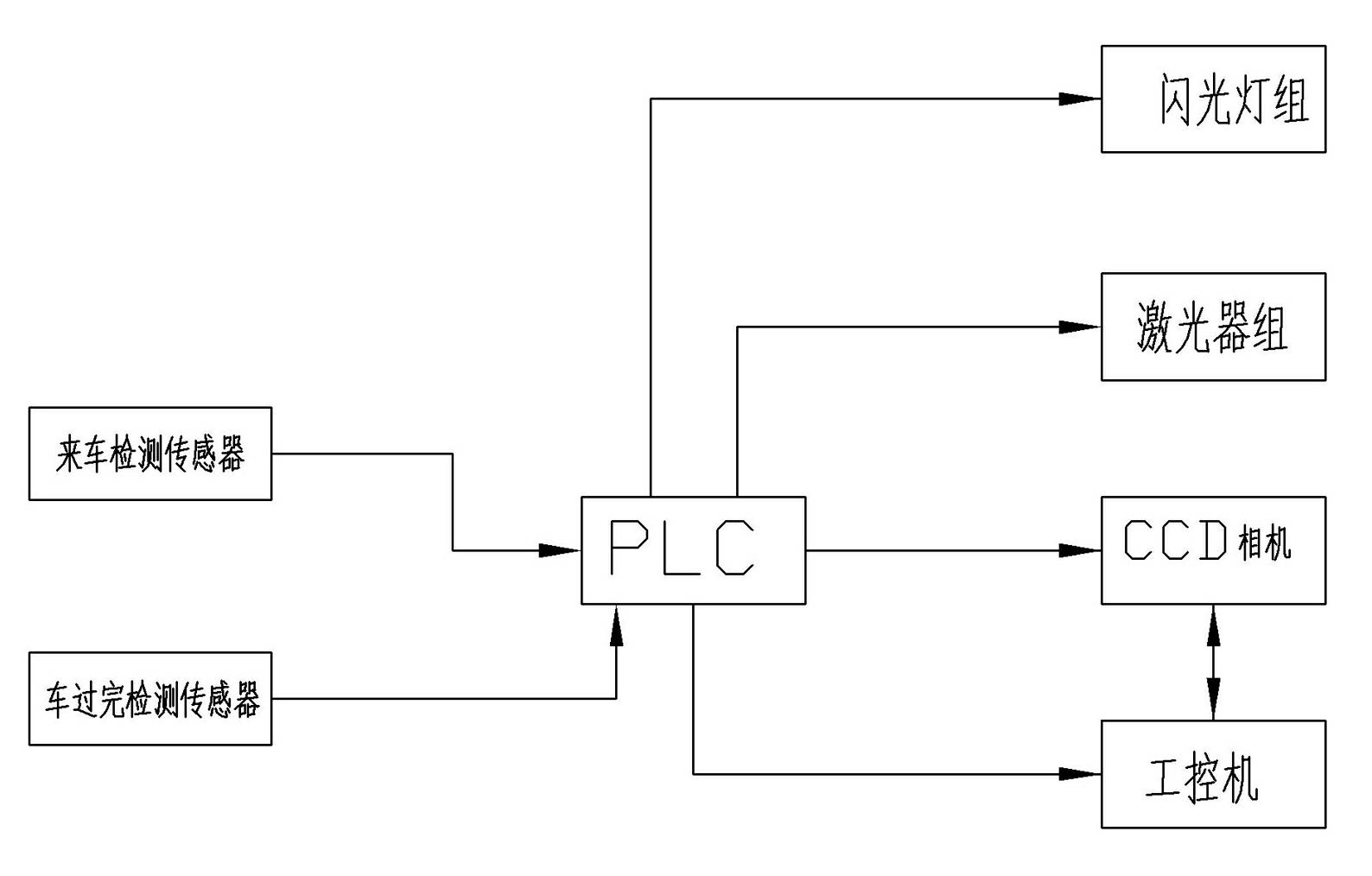
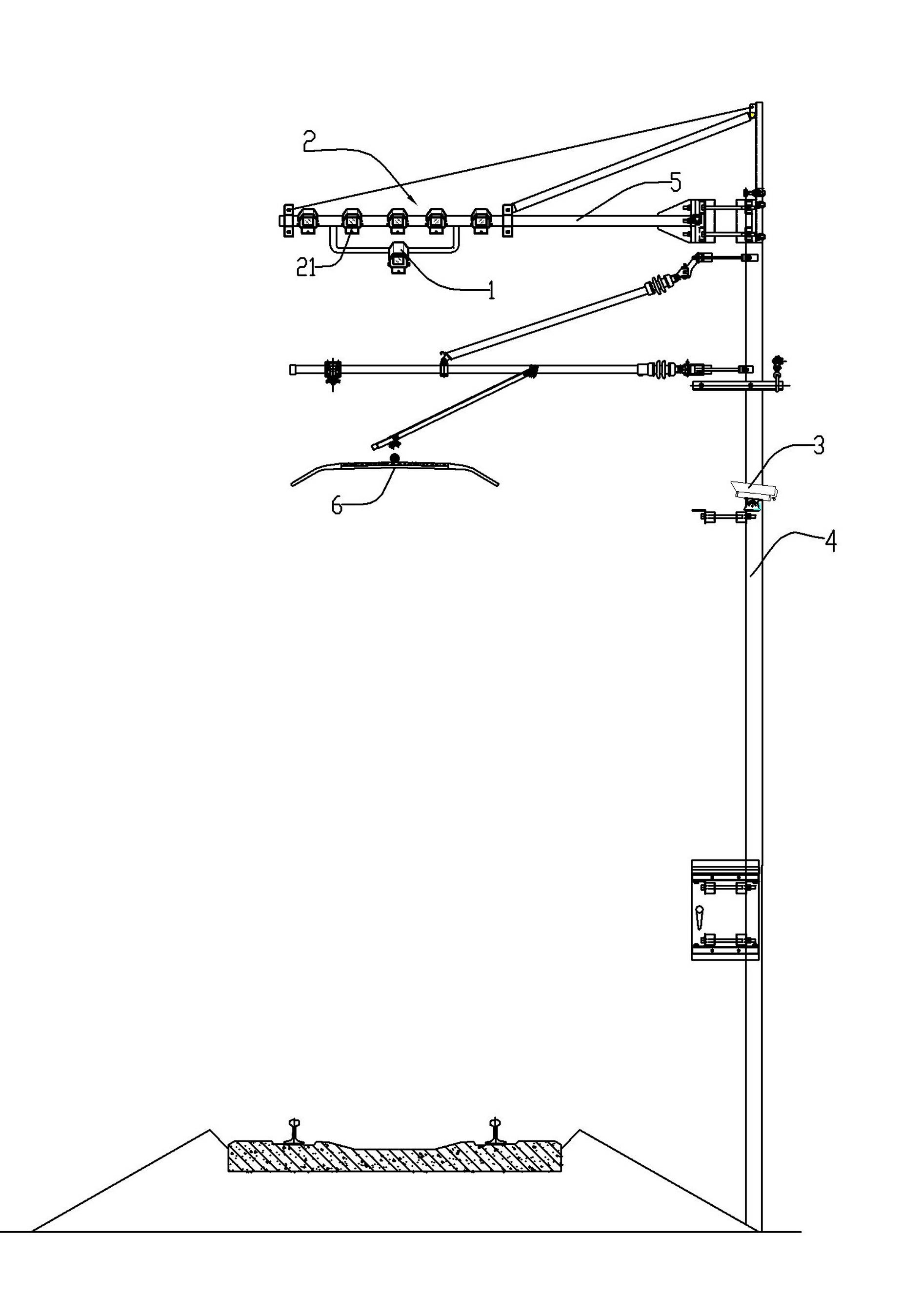
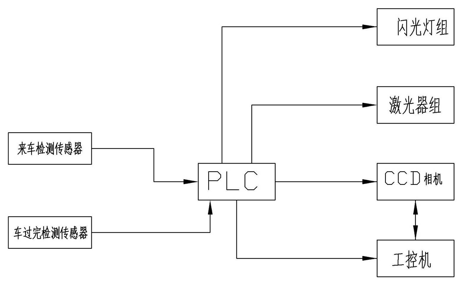
[0009] like figure 1 , figure 2 A pantograph monitoring system, including a CCD camera 1 installed obliquely above the monitoring place for taking pictures of the side of the pantograph head part, a laser group 2 for irradiating the side of the pantograph 6 at the monitoring place, Described laser group comprises a plurality of lasers 21, is arranged parallel to each other, and the top of monitoring place is also installed with the flashlight group 3 that is made of a plurality of flashlights; CCD camera, laser group and flashlight group connect PLC controller, by PLC controller To control its opening and closing, the PLC controller is also connected to an industrial computer. The industrial computer and the CCD camera are connected through a broadband network, and the photos transmitted by the CCD camera can be received through the broadband network, and stored and processed. Described laser group can be installed on the cantilever 5 that stretches out above contact line t...


PUM


Abstract

The invention discloses a pantograph monitoring system, which comprises a CCD (Charge Coupled Device) camera, a laser group and a flash light group, wherein the CCD camera, the laser group and the flash light group are connected with a PLC (Programmable Logic Controller) and are controlled to be switched on/off by the PLC controller; the PLC controller is also connected with an industrial computer; and the industrial computer is connected with the CCD camera through a broadband network, and can receive, store and process photos sent by the CCD camera through the broadband network. The industrial computer is used for analyzing and processing an image of a part of the side face of the pantograph head of the pantograph, taken by using the CCD, so that the wearing situation of a sliding plate on the top of the pantograph head of the pantograph and the deformation situations of cleats on two sides can be known clearly and vividly. By adopting the pantograph monitoring system, the wearing situation of the sliding plate of the pantograph and the deformation situations of the cleats can be automatically monitored, high efficiency and high accuracy are achieved, error judgment does not occur easily, and the bow net accident is avoided more reliably.

Description

technical field [0001] The invention relates to a system for monitoring the wear condition of the sliding plate surface of the pantograph used on the roof of the rail electric traction locomotive and the deformation condition of the horn of the pantograph. Background technique [0002] A pantograph is an electrical device installed on the top of an electric traction locomotive to obtain electrical energy from the catenary. It usually consists of a bow head part, a hinge part, a chassis and a transmission mechanism. The bow head part includes a slide plate frame, a slide plate mounted on the frame, and horns on both sides of the frame. The slide plate is in sliding contact with the contact line to receive current. In order to ensure the smooth circulation of the pantograph traction current, the sliding plate on the top of the pantograph and the contact line of the catenary must be in reliable contact with a certain contact pressure. However, the pantograph travels at high sp...

Claims


Application Information

Patent Timeline
IPC IPC(8): G01B11/00G01B11/06G01B11/16
Inventor 朱晓东
Owner DONGGUAN NANNAR ELECTRONICS TECH
Why Eureka
Try Eureka