
Optical switch system and signal light feedback control method

A technology of optical switch and signal light, which is applied in the direction of optical control, optical waveguide coupling, non-electric variable control, etc., can solve the problems of high cost and low accuracy of optical path positioning, and achieve the goal of reducing cost and impact Effect

Inactive Publication Date: 2011-07-27
HUAWEI TECH CO LTD
View PDF4 Cites 18 Cited by
  • Summary
  • Abstract
  • Description
  • Claims
  • Application Information

AI Technical Summary

Problems solved by technology

[0004] However, each branch of the optical switch system in the prior art requires a Tap and PD, which is very expensive for an optical switch with a large branch ratio, and the accuracy of optical path positioning is low

Method used


Image

  • Optical switch system and signal light feedback control method
  • Optical switch system and signal light feedback control method
  • Optical switch system and signal light feedback control method

Examples


Embodiment Construction

[0027] In order to make the purpose, technical solutions and advantages of the embodiments of the present invention clearer, the technical solutions in the embodiments of the present invention will be clearly and completely described below in conjunction with the drawings in the embodiments of the present invention. Obviously, the described embodiments It is a part of embodiments of the present invention, but not all embodiments. Based on the embodiments of the present invention, all other embodiments obtained by persons of ordinary skill in the art without creative efforts fall within the protection scope of the present invention.

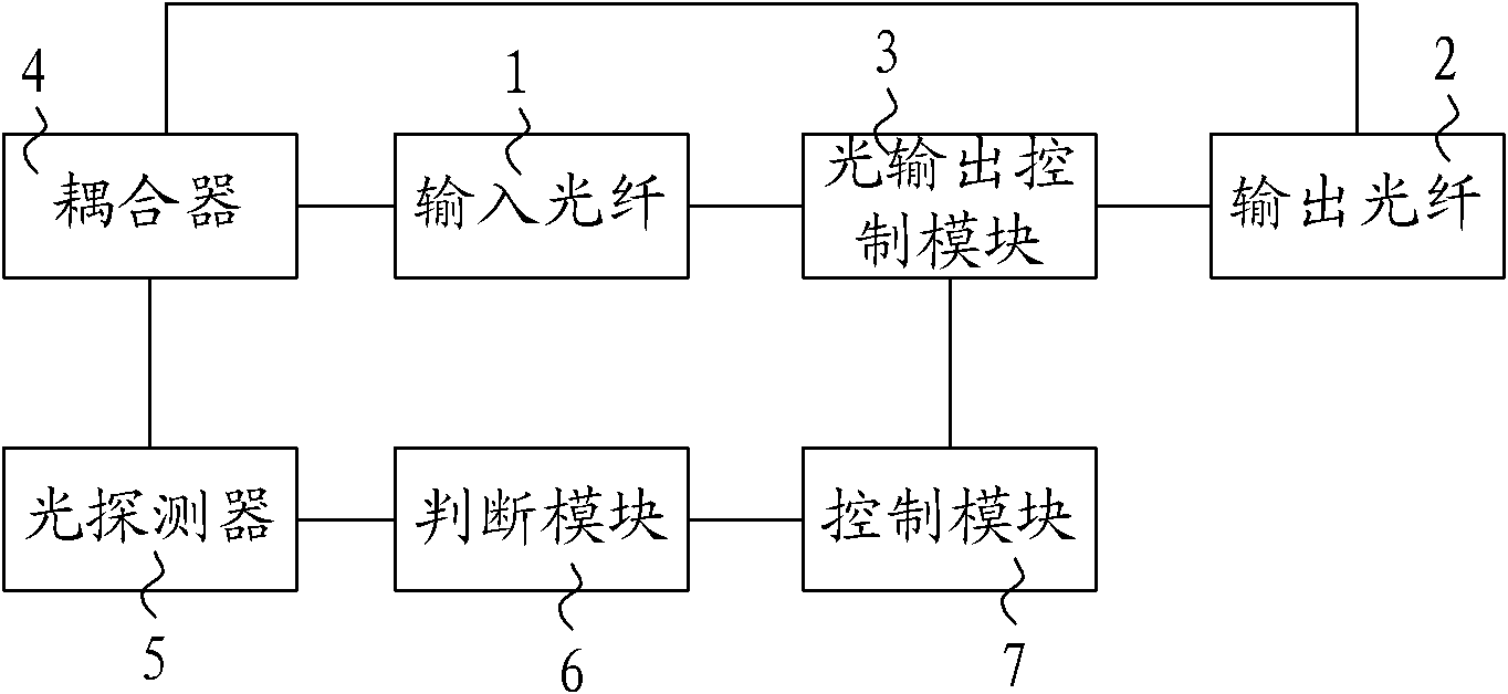
[0028] figure 2 It is a schematic structural diagram of Embodiment 1 of the optical switch system of the present invention, such as figure 2 As shown, this embodiment provides an optical switch system, which can be specifically applied to a mechanical optical switch, and can also be applied to a micro-electromechanical system (Micro Electro Mec...


PUM


Abstract

The invention discloses an optical switch system and a signal light feedback control method. The optical switch system comprises an input optical fiber, an output optical fiber and an optical output control module, wherein a reflecting film is coated on an end face of the output optical fiber; and the optical switch system also comprises a coupler, a photodetector, a judging module and a control module, wherein the coupler is connected with the input optical fiber; the reflecting film is used for reflecting the signal light which is output from the optical output control module to the output optical fiber and reflecting the reflected output signal light in the coupler along an original path; the coupler is used for splitting the output signal light and extracting the signal light in a first preset ratio from the output signal light and inputting the signal light into the photodetector; and the judging module is used for comparing light energy of the output signal light which is detected by the photodetector with light energy of the input signal light which is initially acquired. The invention also provides a signal light feedback control method. Compared with the prior art, the invention greatly reduces the cost.

Description

technical field [0001] The invention relates to photoelectric technology, in particular to an optical switch system and a feedback control method for signal light. Background technique [0002] With the rapid development of Fiber To Home (hereinafter referred to as: FTTH) technology, its market scale is huge, the distribution of end users and optical link branches involved in the access network is complex, and the entire network uses all-fiber wiring, which cannot be utilized Therefore, it is necessary to use the optical link detection system to monitor network maintenance and ensure network quality. At present, the monitoring system mainly uses Optical Time Domain Reflectometer (OTDR) to detect link performance, but its cost is high, so 1*N optical switch is used to reduce the usage through N access terminals. cost. [0003] In order to ensure the long-term stability of the optical switch, a feedback mechanism is usually added to the optical switch system to ensure that t...

Claims


Application Information

Patent Timeline
Patent Type & Authority Applications(China)
IPC IPC(8): G02B6/35G05D25/02
CPCG02B6/3518G02B6/35G05D25/02G02B6/3504
Inventor 王世军温运生赵峻
Owner HUAWEI TECH CO LTD
Learn More