Microwave staring imaging method

A technology of microwave staring and microwave imaging, which is used in the reflection/re-radiation of radio waves, radio wave measurement systems, and the use of re-radiation.

A technology of microwave staring and microwave imaging, which is used in the reflection/re-radiation of radio waves, radio wave measurement systems, and the use of re-radiation.

CN102141618BInactive Publication Date: 2012-10-10UNIV OF SCI & TECH OF CHINA

Image

  • Microwave staring imaging method
  • Microwave staring imaging method
  • Microwave staring imaging method

Examples


Embodiment Construction

[0049]Embodiments of the present invention are described in detail below, examples of which are shown in the drawings, wherein the same or similar reference numerals designate the same or similar elements or elements having the same or similar functions throughout. The embodiments described below by referring to the figures are exemplary only for explaining the present invention and should not be construed as limiting the present invention.

[0050] The core idea of ​​the scheme proposed by the present invention is:

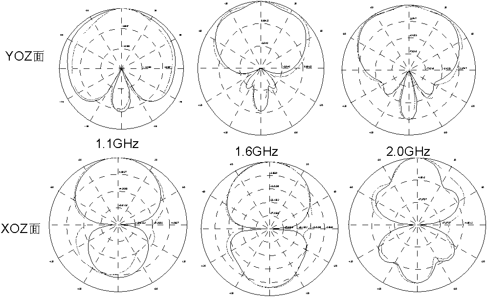
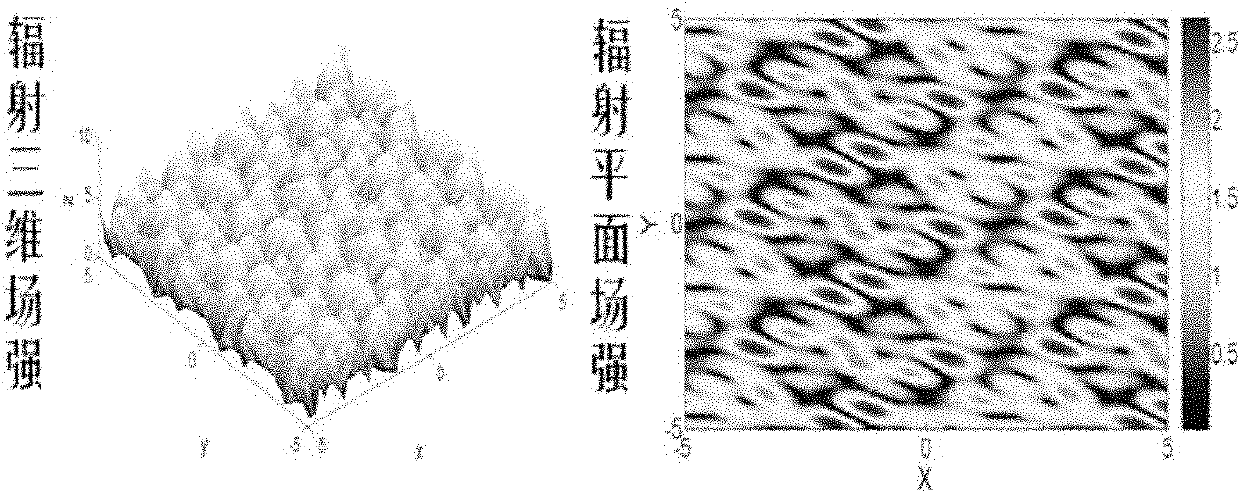
[0051] The new method of microwave staring imaging based on the space-time two-dimensional random radiation field and correlation processing constructs the mouth surface field with special random distribution characteristics, and forms a spatial random radiation field that meets special requirements in the beam coverage area through propagation. At this time, the antenna radiation is no longer a simple point source radiation, but a multi-phase center radiation, a...


PUM


Abstract

The embodiment of the invention provides a microwave staring imaging method based on a time and space two-dimensional random radiation field and associative processing, which comprises the following steps that an antenna aperture field is specially required to randomly radiate a target area covered by a wave beam, and forming the noncorrelation characteristic that the radiation field with the time and space two-dimensional random distribution characteristics is required to simultaneously meet the time dimension and the space dimension; and after the radiation field is interacted with a detected target, a receiver is used for receiving an echo scattering field signal and extracting the target space information distribution of an area to be detected through receiving the correlated imaging process of a scattering filed and a known radiation field to realize the microwave staring imaging. With the adoption of the technical scheme provided by the invention, the defect that the traditionalreal aperture radar spatial resolution depends on the antenna aperture is overcome through the correlated microwave staring imaging of the time and space two-dimensional radiation field, and the high-resolution microwave staring imaging can be realized.

Description

technical field [0001] The invention relates to imaging technology in the fields of radar, microwave remote sensing and precise guidance, in particular, the invention relates to a microwave staring imaging method. Background technique [0002] Traditional real-aperture imaging radars include beam scanning radars, phased array radars, and focal plane imaging radars. For beam scanning radar, due to the limitation of beam coverage, it is necessary to use mechanical scanning to change the beam direction. like figure 1 Shown is a schematic diagram of a conventional antenna beam direction. Phased array radar replaces mechanical scanning with computer-controlled beam formation and scanning. It controls the phase and amplitude of each unit of the array antenna to form a beam that satisfies certain distribution characteristics in space, and can change its scanning direction, overcoming mechanical scanning. bring about problems. Focal plane imaging radar uses the deflection of the...

Claims


Application Information

Patent Timeline
10 Oct 2012
Publication
CN102141618B
IPC
G01S13/89; G01S7/41
Inventors
王东进; 徐浩