Clamping structure for fixture

A clamp and clamp plate technology, applied in the field of clamping structures and compact clamping structures for clamps, can solve the problems of the pressing point moving, inapplicable, insufficient space, etc., to avoid clamping deformation, avoid clamps becoming larger, The effect of the compact structure of the fixture

Inactive Publication Date: 2011-08-10
HUBEI HANDAN MECHATRONICS CO LTD
View PDF0 Cites 6 Cited by
  • Summary
  • Abstract
  • Description
  • Claims
  • Application Information

AI Technical Summary

Problems solved by technology

When the distance between the two pressure points is very small, due to the large volume of the hydraulic cylinder and insufficient space, it is difficult to realize
When a single hydraulic cylinder is used to drive the hinged floating double pressure point structure, a single hydraulic cylinder can simultaneously compress two points with a small distance, but due to the movement of the compression point caused by floating, the compression point cannot be completely aligned with the positioning point Positive, it will cause a certain degree of compression deformation, which is not suitable for occasions that require precise compression positions

Method used


Image

  • Clamping structure for fixture
  • Clamping structure for fixture
  • Clamping structure for fixture

Examples


Embodiment Construction

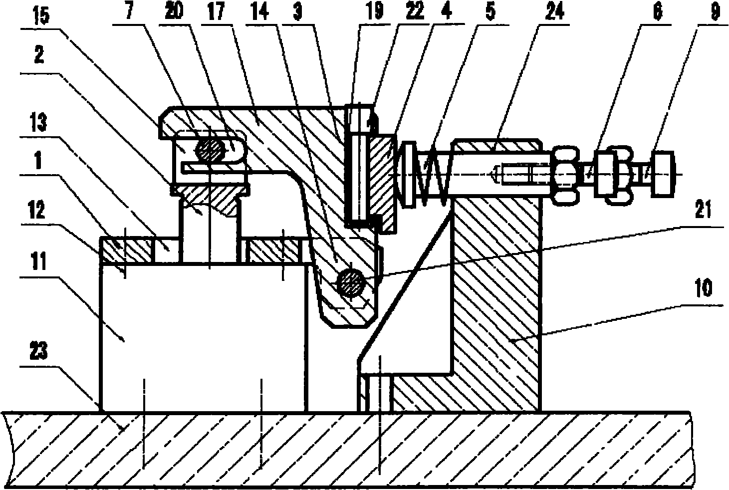
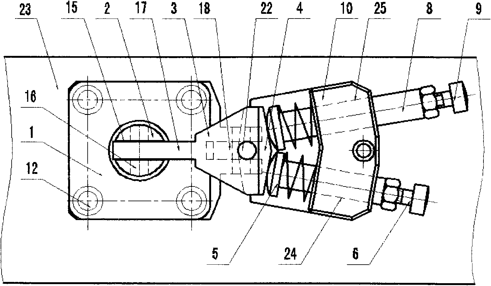
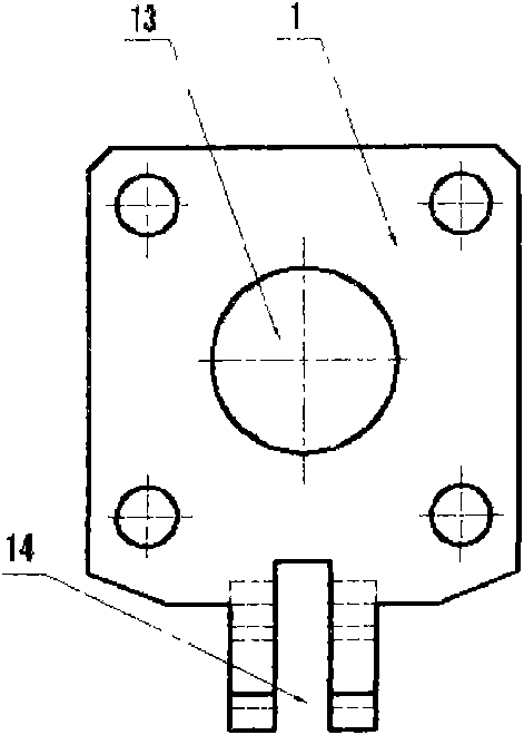
[0017] figure 1 , figure 2 Among them, the present invention mainly includes connecting plate 1, connecting rod 2, crank 3, pressing plate 4, first pressing rod 5, first ejector rod 6, pin 7, second pressing rod 8, second ejector rod 9, base 10 And hydraulic cylinder 11 etc. constitute. The connecting plate 1 is fixed on the hydraulic cylinder 11 by screws 12, a hole 13 is opened in the middle, and a square groove 14 is opened on one side. The lower end of the connecting rod 2 passes through the hole 13 and is fixedly connected with the hydraulic cylinder 11. The upper end of the connecting rod 2 is provided with a square groove 15, and the side is provided with a pin hole 16. One end of the crank 3 is a square block 17, a square boss 18 is arranged at the bottom, and a square groove 19 is arranged on the side of the other end. The size of the square block 17 matches the square groove 15, and the size of the square boss 18 matches the square groove 14. A U-shaped groove 2...


PUM


Abstract

The invention discloses a clamping structure of a fixture. A hydraulic cylinder and a base are fixed on a fixture plate, the lower end of a connecting rod is fixed on the hydraulic cylinder after penetrating through a connecting plate, and the connecting rod is provided with a groove at the upper end and pin holes in the side face; the bottom of a crank is arranged in the connecting plate and connected by using pins at clamping parts; one end of the crank is a square block, and the side face at the other end of the crank is provided with a square groove; the square block of the crank is arranged in the groove of the connecting rod and is provided with a U-shaped groove, and the pins penetrate through the pin holes; one end of a pressing plate is embedded into the crank through the square groove; the upper end of the base is provided with two orienting holes; one end of a first compression rod is in contact with the pressing plate, and the other end of the first compression rod is fixedly connected with one end of a first push rod after penetrating through one of the orienting holes in the base; and one end of a second compression rod is in contact with the pressing plate, and the other end of the second compression rod is fixedly connected with a second push rod after penetrating through the other oriented hole in the base. In the invention, the accurate compaction on two pressing points with a small spacing can be realized by using a single hydraulic cylinder, the traditional hinge-type floating dual-pressing point structure is replaced, and orienting devices are arranged on the pressing points to accurately orient the positions of the pressing points.

Description

technical field [0001] The invention relates to a clamping structure in the field of mechanical processing, in particular to a compact clamping structure for a clamp. Background technique [0002] In the field of mechanical processing, it is often required that the position of the pressure point be very accurate to prevent the compression deformation caused by the misalignment of the position of the pressure point and the positioning point. In some hydraulic suspension fixtures that require precise pressure point positions, a single hydraulic cylinder is generally used to drive a clamping point to ensure precise pressure point position compression. When the distance between the two pressure points is very small, it is difficult to realize due to the large volume of the hydraulic cylinder and insufficient space. When a single hydraulic cylinder is used to drive the hinged floating double pressure point structure, a single hydraulic cylinder can simultaneously compress two po...

Claims


Application Information

Patent Timeline
Patent Type & Authority Applications(China)
IPC IPC(8): B23Q3/06
Inventor 许亚辉高海涛杨定国陶爱容孟巍张旗龚松
Owner HUBEI HANDAN MECHATRONICS CO LTD
Why Eureka
Try Eureka