Flexible four-DOF (Degree of Freedom) mechanical arm

A technology with a degree of freedom and manipulators, applied in the field of manipulators, can solve the problems of small parts, difficult to grasp, large manipulators, etc., and achieve the effect of high reliability, small size and high grasping accuracy

Active Publication Date: 2011-08-10
SHANDONG ATAW IND ROBOT TECH
View PDF7 Cites 4 Cited by
  • Summary
  • Abstract
  • Description
  • Claims
  • Application Information

AI Technical Summary

Problems solved by technology

[0002] With the development of technology, more and more manipulators are used in various fields, especially in automatic production lines. However, most of the manipulators used in automatic production lines are relatively large, which is not suitable for the production of small parts, because tiny parts are not easy to clamp If it is not supported, the manufacturing requirements for the manipulator will be very strict. It is necessary to achieve high-precision grasping and improve work reliability.
For example, in the production of civilian power switches, due to the small size of each part, it is not easy to grasp, and currently it is still installed manually, which is very inconvenient

Method used


Image

  • Flexible four-DOF (Degree of Freedom) mechanical arm
  • Flexible four-DOF (Degree of Freedom) mechanical arm
  • Flexible four-DOF (Degree of Freedom) mechanical arm

Examples


Embodiment 1

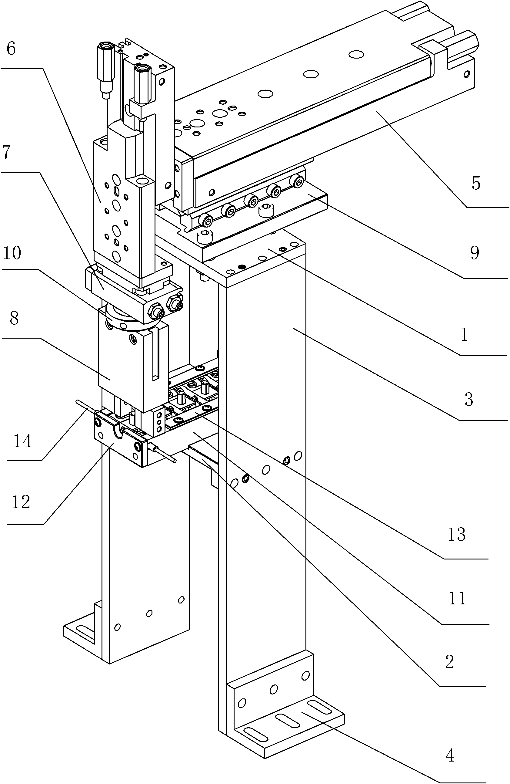
[0014] Embodiment one: the bottom of the horizontal displacement cylinder 5 is fixed on the connector 9, the connector 9 is fixed on the horizontal fixed plate 1 by bolts, the bottom of the vertical displacement cylinder 6 is fixed on one end of the horizontal displacement cylinder 5, and the vertical displacement cylinder 6 The end is fixed with a rotary cylinder 7, and the rotary cylinder 7 is fixed with parallel air claws through a flange 10.

Embodiment 2

[0015] Embodiment two: the bottom of the horizontal displacement cylinder 5 is fixed on the connector 9, the connector 9 is fixed on the horizontal fixed plate 1 by bolts, the bottom of the vertical displacement cylinder 6 is fixed on one end of the horizontal displacement cylinder 5, and the vertical displacement cylinder 6 The end is fixed with a rotary cylinder 7, and the rotary cylinder 7 is fixed with an inner clamping air claw 81 or a slotted air claw 82 through the flange 10.

Embodiment 3

[0016] Embodiment three: the bottom of the horizontal displacement cylinder 5 is fixed on the connector 9, the connector 9 is fixed on the horizontal fixed plate 1 by bolts, the bottom of the vertical displacement cylinder 6 is fixed on one end of the horizontal displacement cylinder 5, and the vertical displacement cylinder 6 The end is fixed with parallel air claws through the flange 10.

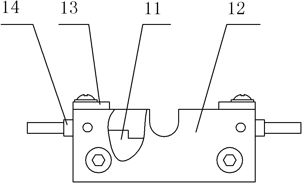
[0017] Working principle: as Figure 5 As shown, the vertical displacement cylinder 6 drives the air claw 8 to move downward to the storage pipe 11, the air claw 8 grabs the material, the vertical displacement cylinder 6 drives the air claw 8 to move upward, and when it moves to the top, the horizontal displacement cylinder 5 Drive the vertical displacement cylinder 6 to move forward to the specified position, and at the same time, driven by the rotary cylinder 7, the air claw 8 rotates 90°, the vertical displacement cylinder 6 drives the air claw 8 to move downward, and the air claw 8 put...


PUM


Abstract

The invention relates to a flexible four-DOF (Degree of Freedom) mechanical arm, relating to mechanical arms. The flexible four-DOF mechanical arm comprises a bracket device and a pneumatic device, wherein the bracket device comprises a horizontal fixed plate, a material storage bracket, vertical brackets and fixed baseboards, wherein both sides of the horizontal fixed plate are respectively fixed with the vertical brackets through positioning pins and bolts; the bottoms of the vertical brackets are fixed with the fixed baseboards through bolts; the material storage bracket is fixed between the two vertical brackets and provided with a material storing device; the pneumatic device comprises a horizontal displacement cylinder, a vertical displacement cylinder, a rotary cylinder and a pneumatic claw, wherein the bottom of the horizontal displacement cylinder is fixed on a connecting piece; the connecting piece is fixed on the horizontal fixed plate through bolts; the bottom of the vertical displacement cylinder is fixed on one end of the horizontal displacement cylinder; the tail end of the vertical displacement cylinder is fixed with the rotary cylinder; and the rotary cylinder is fixed with the pneumatic claw through a flange. In the invention, the blocky parts or the parts with inner holes can be conveniently grabbed and arranged on specified positions, and the invention has the advantages of high grabbing accuracy and reliability and small size.

Description

technical field [0001] The invention relates to a manipulator, in particular to a flexible four-degree-of-freedom manipulator. Background technique [0002] With the development of technology, more and more manipulators are used in various fields, especially in automatic production lines. However, most of the manipulators used in automatic production lines are relatively large, which is not suitable for the production of small parts, because tiny parts are not easy to clamp If it is not supported, the manufacturing requirements for the manipulator will be very strict, not only to achieve high-precision grasping but also to improve work reliability. For example, in the production of civil power switches, due to the small size of each part, it is not easy to grasp, and currently it is still installed manually, which is very inconvenient. Contents of the invention [0003] The object of the present invention is to provide a flexible four-degree-of-freedom manipulator to solv...

Claims


Application Information

Patent Timeline
Patent Type & Authority Applications(China)
IPC IPC(8): B25J9/08B25J9/10B25J15/00
Inventor 张乐贡李元波张浦
Owner SHANDONG ATAW IND ROBOT TECH
Why Eureka
Try Eureka