Active rope tensioning device for wire rope

A technology of steel wire rope and rope tensioner, which is applied in hoisting device, clockwork mechanism, etc. It can solve the problems of wire rope slack and random buckling, and achieve the effect of avoiding random buckling

Inactive Publication Date: 2012-10-10
倪景明
View PDF5 Cites 2 Cited by
  • Summary
  • Abstract
  • Description
  • Claims
  • Application Information

AI Technical Summary

Problems solved by technology

[0004] The object of the present invention is to provide an active rope tightening device for steel wire ropes, which actively applies a tension force to the steel wire ropes during the process of unwinding the ropes, so as to solve the problem that the steel wire ropes are slack and randomly buckled.

Method used


Image

  • Active rope tensioning device for wire rope
  • Active rope tensioning device for wire rope
  • Active rope tensioning device for wire rope

Examples


Embodiment 1

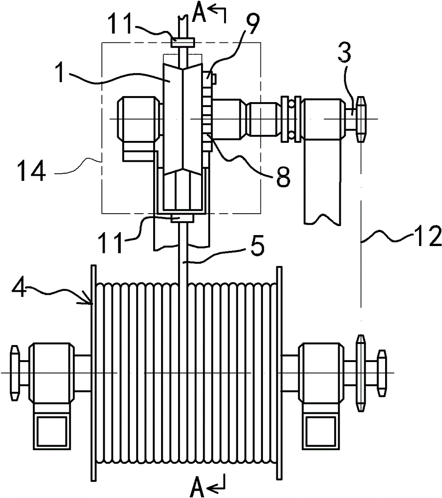
[0025] Embodiment one: see attached Figure 1~3 Shown:

[0026] An active rope tightening device for steel wire ropes, comprising a rope tightening wheel 1, a pressure roller 2, a transmission shaft 3 and a ratchet mechanism.

[0027] The rope tightening wheel 1 and the pressing roller 2 are arranged side by side for rotation and support, and the central axes of the rope tightening wheel 1 and the pressing roller 2 are parallel to each other. The wheel surface of described tight rope wheel 1 and the wheel surface of pressure roller 2 match, and the wheel surface section of concrete tight rope wheel 1 is concave V shape, and the wheel surface of pressure roller 2 is plane, and the two sides of pressure roller 2 The side is provided with positioning plate 13, and this positioning plate 13 plate edges protrude on both sides of the pressure roller 2, and the tight rope wheel 1 just embeds between the two positioning plate 13 plate edges, so that the tight rope wheel 1 wheel surfa...

Embodiment 2

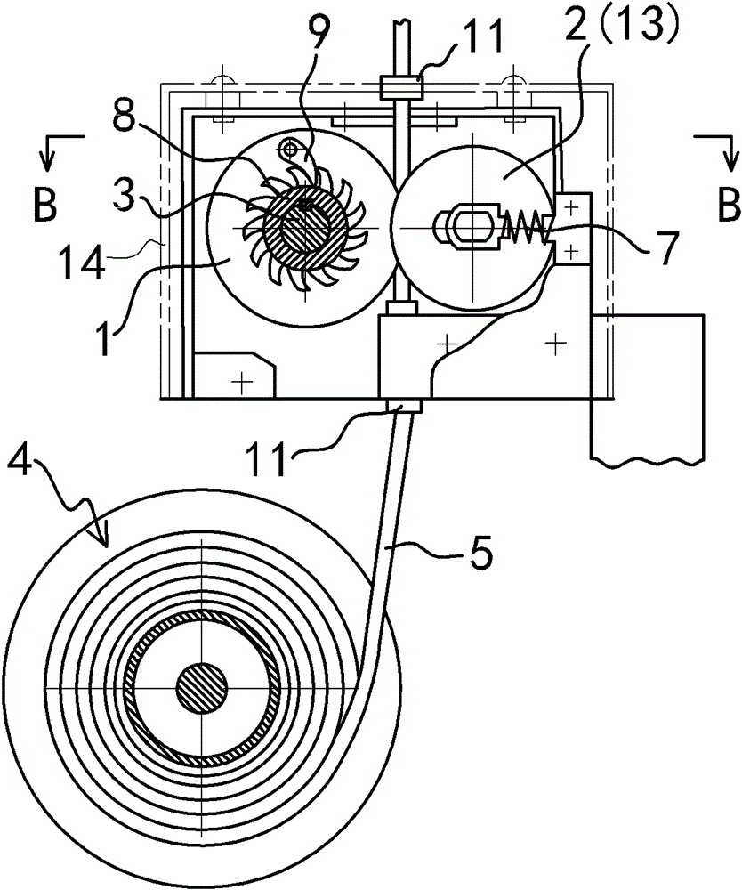
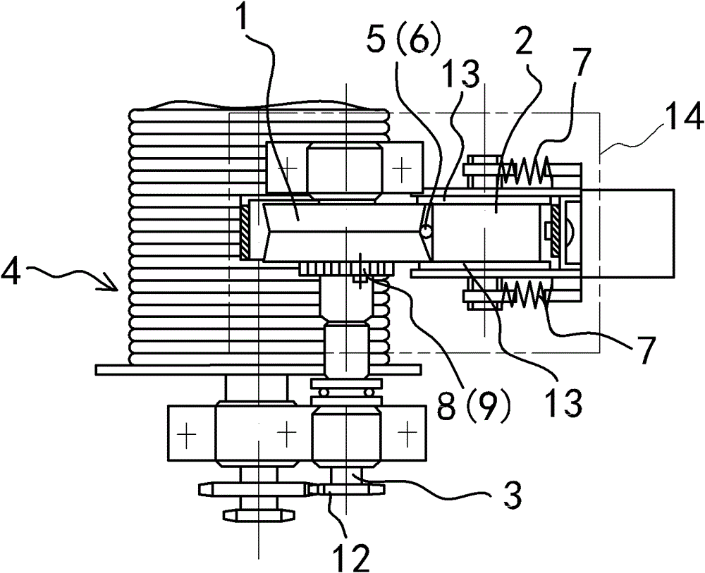
[0034] Embodiment two: see attached Figure 4 Shown:

[0035]An active rope tensioner for a steel wire rope, comprising a rope tightening wheel 1, a pressure roller 2, a transmission shaft 3 and a ratchet mechanism, the only difference from Embodiment 1 is that the ratchet mechanism is an internally connected ratchet mechanism, which includes Ratchet, transmission wheel 10, ratchet 9 and spring; Establish teeth on the inner edge of described tight rope wheel 1 to form described ratchet, described transmission wheel 10 is embedded in the center of tight rope wheel 1 on the described transmission shaft 3, The transmission wheel 10 is fixed or keyed to the transmission shaft 3; the teeth of the corresponding ratchet of the ratchet 9 are hinged on the transmission wheel 10, and the spring acts on the ratchet 9 to make the ratchet 9 and the teeth of the ratchet match.

[0036] Others are the same as those in Embodiment 1, and will not be repeated here.


PUM


Abstract

The invention discloses an active rope tensioning device for a wire rope. The device is characterized by comprising a rope tensioning wheel, a pressure roller wheel, a transmission shaft and a ratchet mechanism, wherein the rope tensioning wheel and the pressure roller wheel rotate in parallel and support each other; the wheel surface of the rope tensioning wheel is matched with the wheel surfaceof the pressure roller wheel, and a compaction gap for threading the wire rope on the rope winding wheel of a wire rope suspension type lifting apparatus is formed between the two wheel surfaces; thetransmission shaft is arranged along the central axis of the rope tensioning wheel, and is in transmission connection with the rope winding wheel of the wire rope suspension type lifting apparatus; the transmission shaft and the rope tensioning wheel are in transmission connection through the ratchet mechanism to form a one-way transmission structure; and when the rope winding wheel of the wire rope suspension type lifting apparatus releases the rope, the rope tensioning wheel is driven by the transmission shaft to move actively, and the linear velocity of the wheel surface of the rope tensioning wheel is greater than the maximum rope releasing velocity of the rope winding wheel of the wire rope suspension type lifting apparatus so as to tension the wire rope. The active rope tensioning device disclosed by the invention effectively ensures that the wire rope is always in a tense state, and prevents the conditions such as loosening of the wire rope, wrong fastening, clamping and the like from happening.

Description

technical field [0001] The invention relates to a wire rope tensioner suitable for a wire rope suspension type lifting device. The so-called wire rope suspension lifting equipment can be high-rise escape equipment, high-altitude operation suspension equipment, small cranes and electric hoists. Background technique [0002] With the progress of society and the development of the times, the number of high-rise buildings in cities increases year by year. When emergencies such as fires, earthquakes, and terrorist attacks occur, how to escape quickly has become a common concern of people. The corridor space of high-rise building is narrow and small, and when breaking out of fire, the intensity of fire is swift and fierce when taking place because of fire, and a lot of people are just suffocated because of dense smoke often before having enough time to escape, lost life. Especially when the fire took place in the lower floors of the building, the victims on the upper floors of th...

Claims


Application Information

Patent Timeline
Patent Type & Authority Patents(China)
IPC IPC(8): B66D1/50
Inventor 倪景明
Owner 倪景明
Why Eureka
Try Eureka