
Anchoring system of floating type photovoltaic power generation platform and construction method of anchoring system

A photovoltaic power generation and anchoring system technology, applied in anchoring arrangements, floating buildings, ship construction, etc., can solve the problems that the anchor rope cannot be used and adjusted, affect the quality of photovoltaic platforms, etc., and achieve the effect of convenient fixing and dismantling

Pending Publication Date: 2022-01-04
华能黑龙江发电有限公司
View PDF0 Cites 0 Cited by
  • Summary
  • Abstract
  • Description
  • Claims
  • Application Information

AI Technical Summary

Problems solved by technology

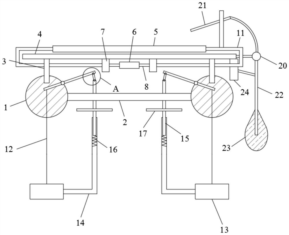
[0003] The existing patent discloses an anchoring system for a floating photovoltaic power generation platform and its construction method. The anchoring system includes two buoys arranged in parallel, and the two buoys are connected to each other through a connecting bridge. Each of the buoys Both ends of the buoy and the side away from the connecting bridge are provided with a connecting structure for connecting the photovoltaic power generation platform, and the bottom of each buoy is provided with an anchoring structure; wherein, the connecting structure includes a rotating shaft and a hinge A connecting piece, the rotating shaft is fixedly connected to the buoy, the hinged connecting piece is sleeved on the rotating shaft and can rotate around the rotating shaft, and the hinged connecting piece is connected to the photovoltaic power generation platform; But there are the following problems: the anchor rope cannot be used and adjusted, and when the water level changes, the photovoltaic power generation platform will still be subject to greater resistance, which will affect the quality of the photovoltaic platform

Method used


Image

  • Anchoring system of floating type photovoltaic power generation platform and construction method of anchoring system
  • Anchoring system of floating type photovoltaic power generation platform and construction method of anchoring system
  • Anchoring system of floating type photovoltaic power generation platform and construction method of anchoring system

Examples


Embodiment Construction

[0025] The following examples are for illustrative purposes only and are not intended to limit the scope of the invention.

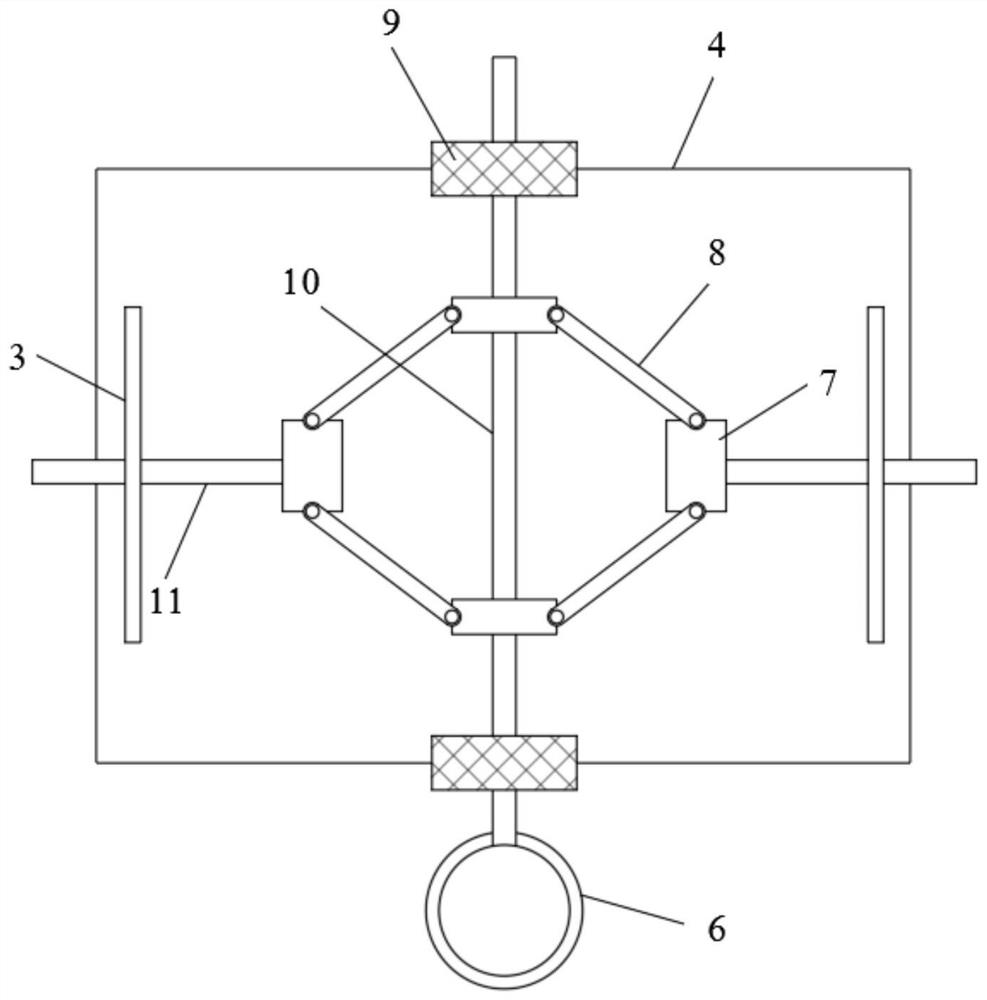
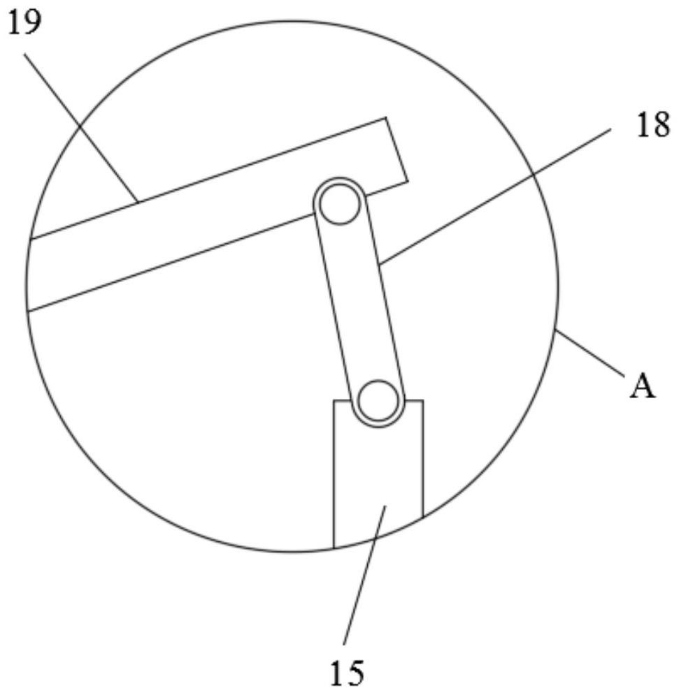
[0026] refer to Figure 1-4 , an anchoring system for a floating photovoltaic power generation platform, including two buoys 1, a platform 2 and a photovoltaic panel 5, the platform 2 is fixed between the two buoys 1, and a support plate 3 is fixed on the upper side wall of each buoy 1 , the upper ends of the two support plates 3 are jointly fixed with a mounting plate 4, the photovoltaic panel 5 is mounted on the mounting plate 4, and the lower side wall of the mounting plate 4 is fixed with two supporting blocks one 9 and two supporting blocks, and the upper supporting block one 9 A bearing is embedded, and the inner ring of the bearing is fixed with a two-way threaded rod 10. The other end of the two-way threaded rod 10 is inserted in the support block two. A swivel 6 is fixed at one end of the two support plates 3, and splints 11 are slidably insert...


PUM


Abstract

The invention discloses an anchoring system of a floating type photovoltaic power generation platform, and the anchoring system comprises two buoys, a platform and a photovoltaic panel; the platform is fixed between the two buoys, a support plate is fixed on the upper side wall of each buoy, a mounting plate is fixed at the upper ends of the two support plates, and the photovoltaic panel is mounted on the mounting plate. The construction method of the anchoring system of the floating type photovoltaic power generation platform comprises the following steps that S1, the buoy and the platform are fixed, and the photovoltaic panel is placed on the mounting plate to be fixed; S2, the end of the rotating plate is fixed to the anchor rope, the buoy is placed on the water surface, and the anchor block sinks into the water surface to be fixed. The system has the advantages that the position of the upper end of the anchor rope is adjusted to ensure that the anchor rope is always in a tightened state, on one hand, the buoy and the platform are prevented from moving when the water level is too low, on the other hand, the buoy and the platform are prevented from being affected by large resistance when the water level is too high, and the photovoltaic efficiency is ensured by regularly cleaning the photovoltaic panel.

Description

technical field [0001] The invention relates to the technical field of photovoltaic power generation, in particular to an anchoring system for a floating photovoltaic power generation platform and a construction method thereof. Background technique [0002] Photovoltaic power generation is a technology that directly converts light energy into electrical energy by using the photovoltaic effect of the semiconductor interface. The floating photovoltaic power generation platform is a platform built on the water surface, and is generally fixed by anchoring. [0003] The existing patent discloses an anchoring system for a floating photovoltaic power generation platform and its construction method. The anchoring system includes two buoys arranged in parallel, and the two buoys are connected to each other through a connecting bridge. Each of the buoys Both ends of the buoy and the side away from the connecting bridge are provided with a connecting structure for connecting the photov...

Claims


Application Information

Patent Timeline
Patent Type & Authority Applications(China)
IPC IPC(8): B63B21/50B63B35/44
CPCB63B21/50B63B35/44B63B2021/505B63B2035/4453Y02E10/50
Inventor 宋子华王利盛宝臣沈玉玲
Owner 华能黑龙江发电有限公司
Learn More