Three-dimensional concentrating solar cell system

A solar cell and concentrating technology, applied in photovoltaic power generation, circuits, electrical components, etc., can solve the problems of increasing the cost of concentrating solar cell modules, and the difficulty of commercializing concentrating solar cell modules.

Inactive Publication Date: 2011-08-10
SOLAPOINT CORP
View PDF1 Cites 6 Cited by
  • Summary
  • Abstract
  • Description
  • Claims
  • Application Information

AI Technical Summary

Problems solved by technology

This will greatly increase the cost of the entire concentrating solar cell modul

Method used


Image

  • Three-dimensional concentrating solar cell system
  • Three-dimensional concentrating solar cell system
  • Three-dimensional concentrating solar cell system

Examples


no. 1 example

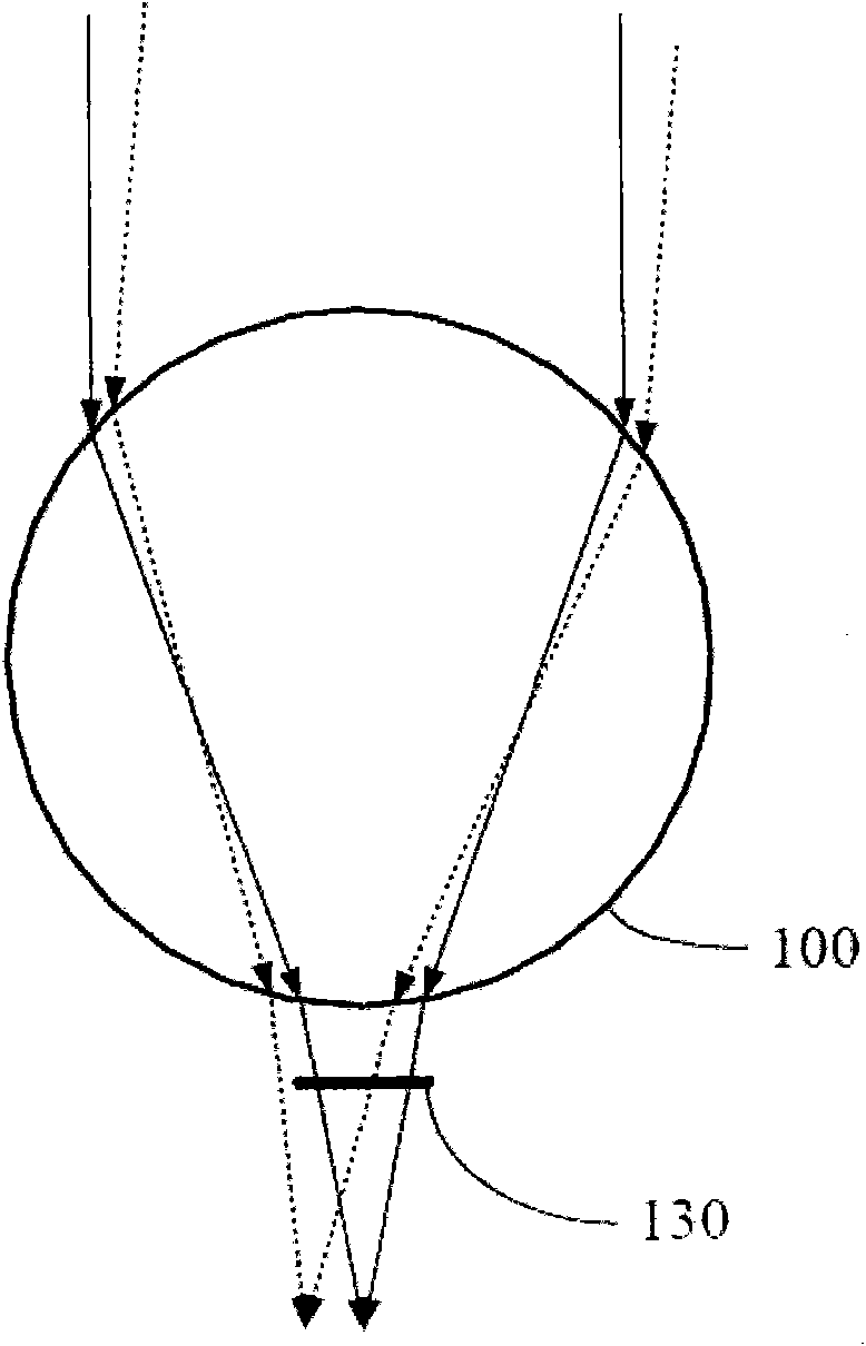
[0039] The first embodiment of the present invention discloses a three-dimensional concentrating solar cell system, which includes a plurality of spherical concentrating elements and a plurality of photovoltaic cells, wherein the plurality of spherical concentrating elements are arranged in a curved surface, and each photovoltaic cell To receive the light collected by a corresponding spherical light concentrating element and convert it into electricity. Referring to (a) to (e) of FIG. 7 , the above-mentioned curved surface includes at least a partial surface of one of the following groups: cylindrical surface, conical surface, spherical surface, ellipsoidal surface, and torus.

[0040] In this embodiment, a plurality of spherical light-collecting elements are arranged to form a curved surface, so no tracking is required for the light source. Besides, the present invention has other advantages, for example, it can replace the currently used floating bodies (floating balls, pont...


PUM


Abstract

The invention provides a three-dimensional concentrating solar cell system in which a sun tracking device is not required. The system comprises a plurality of spherical concentrating elements and a plurality of photovoltaic cells. Since the plurality of spherical concentrating elements are arranged to form a curved surface in sequence, the system is not required to perform tracking aiming at a light source, such as sun and the like, and sufficient power can be provided for application of a user.

Description

technical field [0001] The present invention relates to an optical design of wide-angle condensing light and its alignment method, in particular to a photoelectric element that uses a plurality of spherical condensing elements arranged in a curved surface, which can be used to gather sunlight or indoor light and use A three-dimensional concentrating solar cell system to generate electricity. Background technique [0002] Using solar cells to obtain energy is currently considered to be a more environmentally friendly method compared to other energy sources, such as petrochemical energy, nuclear energy, and water conservancy. Especially when the price of crude oil continues to soar, the many advantages of solar power generation are even more apparent. Furthermore, crude oil will always be used up one day, and solar power generation is an inexhaustible source of energy compared to crude oil. Therefore, governments, research institutes and many private companies are investing ...

Claims


Application Information

Patent Timeline
IPC IPC(8): H01L31/042H01L31/052H01L31/054
CPCY02E10/52Y02E10/50
Inventor 刘台徽
Owner SOLAPOINT CORP
Why Eureka
Try Eureka