
Eddy current rail brake

A rail brake and eddy current technology, which is applied in the field of permanent magnet eddy current rail brakes, can solve problems such as difficulty in reducing the total weight of rail cars, and achieve excellent installability, easy control, and light weight

Active Publication Date: 2013-07-10
NIPPON STEEL CORP
View PDF4 Cites 2 Cited by
  • Summary
  • Abstract
  • Description
  • Claims
  • Application Information

AI Technical Summary

Problems solved by technology

[0011] Therefore, it is difficult to reduce the total weight of railcars using the adsorption type rail brakes, eddy current type rail brakes and adsorption / eddy current type rail brakes proposed in the past

Method used


Image

  • Eddy current rail brake
  • Eddy current rail brake
  • Eddy current rail brake

Examples


example 1

[0064] The invention will be illustrated by the following examples, which are provided for illustration only.

[0065] In order to confirm the effect of the present invention, a conventional electromagnetic disc type eddy current brake (such as the eddy current brake proposed in Japanese Patent Laid-Open No. 2635573), such as Figure 8 An electromagnetic track brake is shown as well as an eddy current track brake according to the invention.

[0066] Figure 4 is a graph showing the relative braking force according to the relative speed of each type of brake obtained by electromagnetic field analysis. Figure 4 The relative speed on the abscissa in the graph of the graph uses 360km / hr as a standard (at 360km / hr, speed value=1.0), and the relative braking force on the ordinate uses 6kN as a standard (at 6kN, the braking force value= 1.0).

[0067] Set the following states for magnetic field analysis,

[0068] Electromagnetic disk type eddy current brake

[0069] Disc materia...


PUM


Abstract

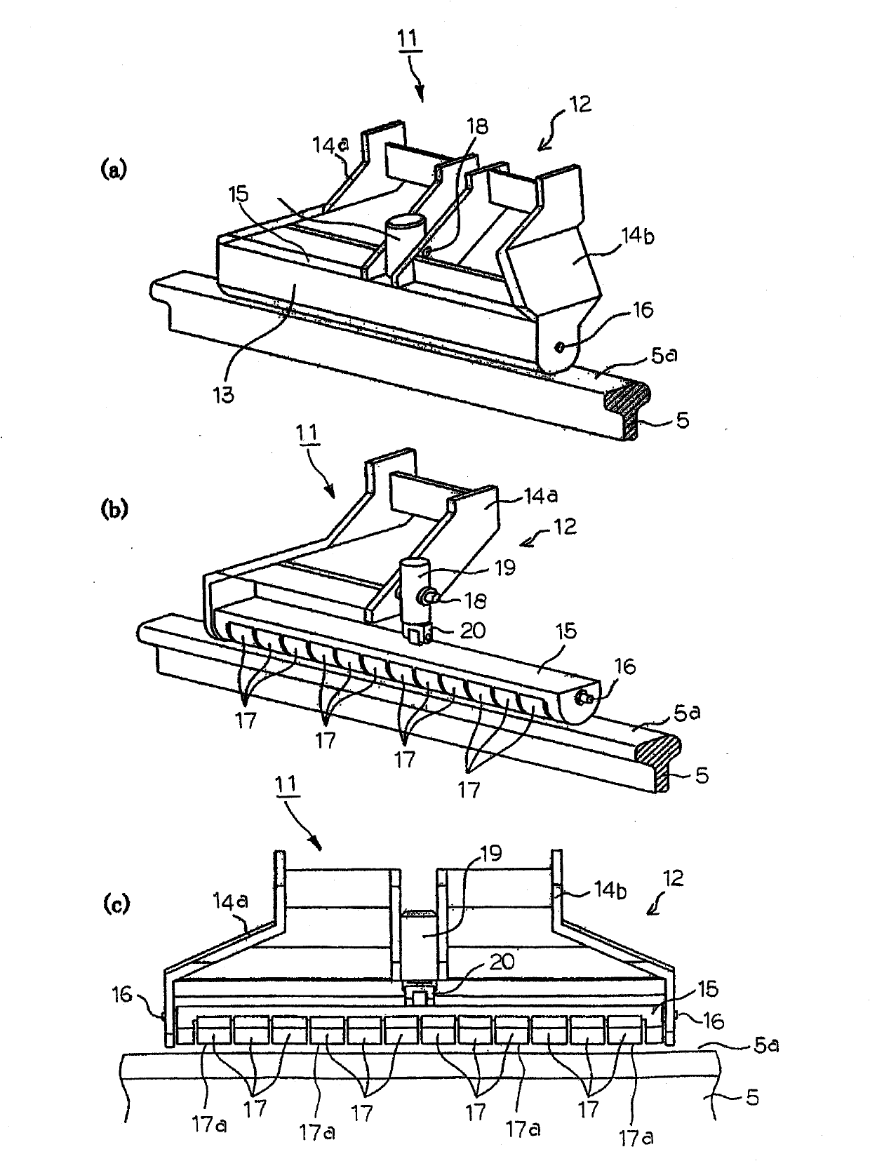
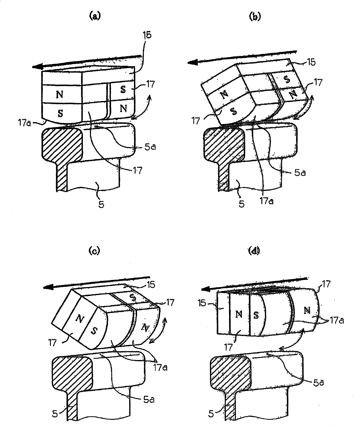
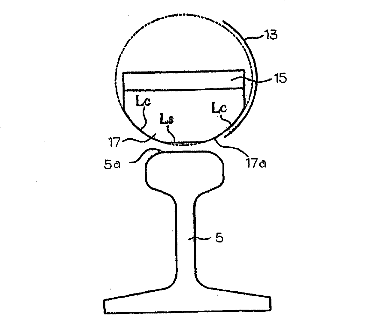
A lightweight eddy current rail brake 11 to be mounted on a bogie frame of a railway car comprises a magnet unit 12 which generates an electromagnetic attraction force with respect to a rail 5 and which comprises an elongated support member 15 and a plurality of permanent magnets 17. The support member 15 is ferromagnetic and extends generally parallel to the direction in which a side beam of a bogie frame extends, and it is rotatable about a shaft which is generally parallel to this direction. A plurality of permanent magnets 17 are arranged on the support member 15 in series and are spaced above a rail 5. At least two adjoining permanent magnets 17 of the plurality of permanent magnets 17 are arranged so as to have different polarities from each other.

Description

technical field [0001] The invention relates to a permanent magnet type eddy current rail brake for decelerating a moving rail vehicle without contacting the rail. Background technique [0002] Adhesion-type braking devices (hereinafter referred to as adhesion brakes) utilizing frictional force (hereinafter referred to as adhesive force) between rails and wheels have been widely used as brakes for rail vehicles on high-speed rail lines. The device is used, for example, as a braking device for bullet trains called Shinkansen in Japan, and is used as a braking device for trams and rail vehicles on conventional (regular speed) track lines, etc. The strength of the sticking determines the maximum braking force produced by the sticky brake. If a large braking force, which exceeds the maximum braking force of the wheel, is applied to the wheel, the wheel will slide on the track instead of rolling, so adhesion can no longer be achieved. This leads to a considerable increase in th...

Claims


Application Information

Patent Timeline
Patent Type & Authority Patents(China)
IPC IPC(8): B61H7/08
CPCB61H7/083B61H7/086
Inventor 今西宪治宫原光雄野口泰隆野上裕斋藤晃北川直树田口均平松慎一朗渡边光章
Owner NIPPON STEEL CORP
Learn More