
Fuel regulating valve of internal-combustion engine

A technology for fuel regulation and internal combustion engines, applied to internal combustion piston engines, combustion engines, charging systems, etc., can solve problems such as fuel waste, uneven mixing of gas and air, and insufficient power of internal combustion engines

Inactive Publication Date: 2012-12-26
CHANGZHOU CHANGRUI TIANLI POWER MACHINERY
View PDF0 Cites 0 Cited by
  • Summary
  • Abstract
  • Description
  • Claims
  • Application Information

AI Technical Summary

Problems solved by technology

[0002] The current gas-fired internal combustion engine uses a composite membrane valve and a separate mixer. Their function is to adjust the air intake of the mixed gas through the throttle when the internal combustion engine has different loads, because the combustible gas is under pressure. Therefore, combustible gas always enters the internal combustion engine under the action of pressure. Due to the lack of a device that can adjust the intake volume of combustible gas according to the air intake volume, this causes the mixing ratio of the mixed gas to be high and low at times, so that Fuel waste and exhaust emissions are not up to standard, internal combustion engine power is insufficient and other consequences. At the same time, the service life of the composite membrane valve is very short, and it is also prone to frequent blockage, which further increases the cost
[0003] Although some existing gas valves have been improved, the improved valve still has the problem of uneven mixing of gas and air.

Method used


Image

  • Fuel regulating valve of internal-combustion engine
  • Fuel regulating valve of internal-combustion engine

Examples


Embodiment Construction

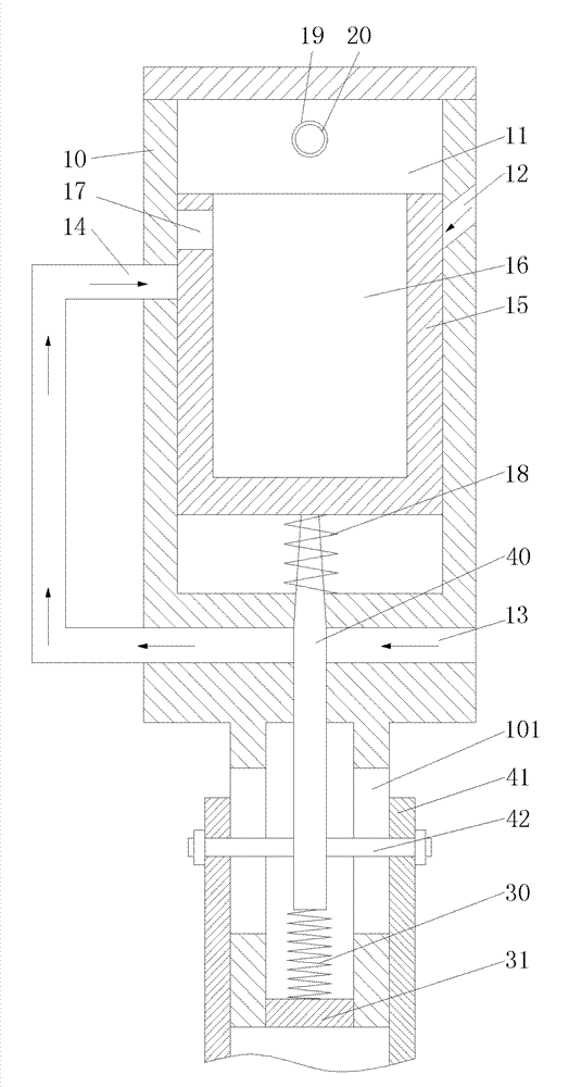
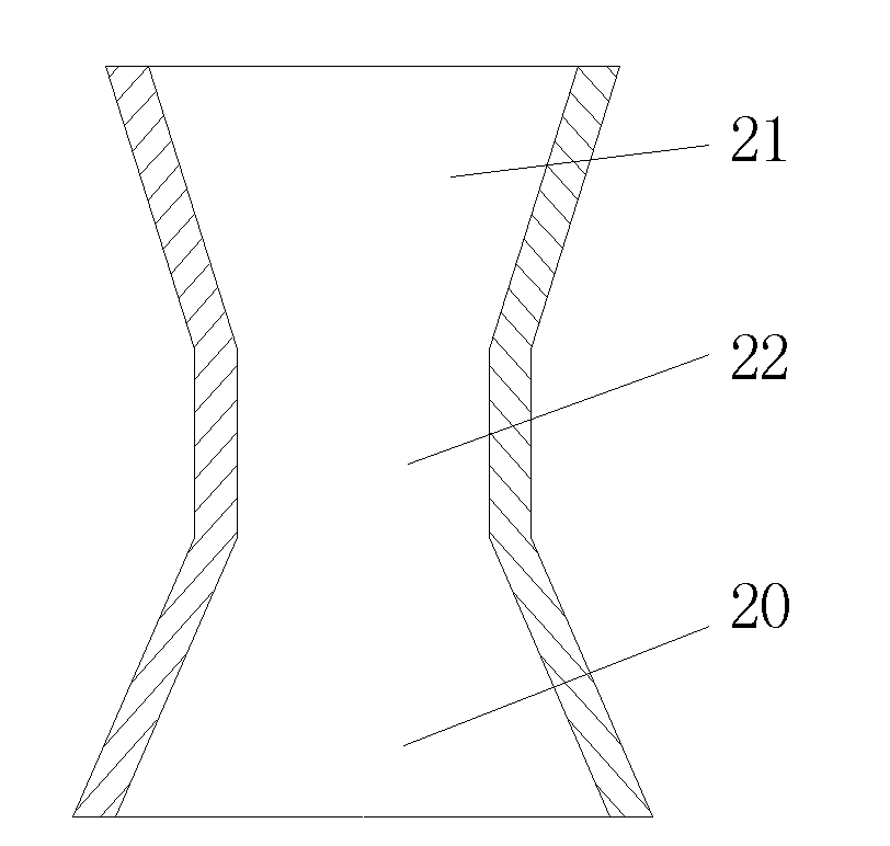
[0011] refer to figure 1 and figure 2 , the internal combustion engine fuel regulating valve of the present invention includes a valve body 10 with an inner cavity 11, an air passage 12 communicating with the cavity is provided on the top of the valve body 10, and the air passage 12 is an inclined through hole, so that air flows from the air passage During middle output, at first directly output in the first mixing chamber 16 of piston 15, valve body 10 bottom is provided with gas channel 13, and this gas channel communicates with the cavity of valve body through gas delivery pipe 14. A piston 15 is set in the inner cavity of the valve body 10, and the upper end of the piston is provided with a first mixing chamber 16, and both air and gas will enter the first mixing chamber 16, and the first mixing chamber is carried out in the first mixing chamber. Mix all at once. A through hole 17 communicating with the first mixing chamber is provided on the side wall of the piston, an...


PUM


Abstract

The invention discloses a fuel regulating valve of an internal-combustion engine; a fuel gas channel is arranged at the lower part of a valve body and is communicated with a cavity of the valve body by a gas pipe, a mixed gas outlet is arranged at the upper part of an inner cavity of the valve body, a guiding device is connected at the position of the mixed gas outlet, a piston is arranged in the inner cavity of the valve body, the upper end of the piston is provided with a first mixing cavity, a through hole communicated with the first mixing cavity is arranged on the side wall of the piston, the lower surface of the piston is connected with one end of a spring, the other end of the spring is connected with the bottom surface of the inner cavity of the valve body, the lower end of the piston is connected with a fuel gas channel control device, the fuel gas channel control device penetrates through the inner cavity of the valve body and the fuel gas channel in sequence and enters a demising hole at the bottom of the valve body, the lower end of the fuel gas channel control device is connected with one end of a resetting device, and the other end of the resetting device is connected with an end cap fixed in the demising hole. In the fuel regulating valve, the fuel gas and the air are mixed more uniformly.

Description

technical field [0001] The invention relates to the technical field of internal combustion engines, in particular to a fuel regulating valve for internal combustion engines using gas. Background technique [0002] The current gas-fired internal combustion engine uses a composite membrane valve and a separate mixer. Their function is to adjust the air intake of the mixed gas through the throttle when the internal combustion engine has different loads, because the combustible gas is under pressure. Therefore, combustible gas always enters the internal combustion engine under the action of pressure. Due to the lack of a device that can adjust the intake volume of combustible gas according to the air intake volume, this causes the mixing ratio of the mixed gas to be high and low at times, so that Fuel waste and exhaust emissions are not up to standard, internal combustion engine power is insufficient and other consequences. At the same time, the service life of the composite mem...

Claims


Application Information

Patent Timeline
Patent Type & Authority Patents(China)
IPC IPC(8): F02M21/04
CPCY02T10/32Y02T10/30
Inventor 张顺
Owner CHANGZHOU CHANGRUI TIANLI POWER MACHINERY
Learn More