
Engine shifting mechanism

A technology for engine and gear shifting, which is applied in the direction of controlled components, mechanical equipment, and mechanical control devices. Long service life, solve the effect of disengagement

Inactive Publication Date: 2011-08-17
力帆科技(集团)股份有限公司
View PDF7 Cites 0 Cited by
  • Summary
  • Abstract
  • Description
  • Claims
  • Application Information

AI Technical Summary

Problems solved by technology

When the design of the gap between the claw and the working surface of the shifting groove is small, it will be difficult for the engine to shift forward and backward; , When the engine is running with high torque, there will be abnormal noises caused by the collision between the claw and the working surface of the slot.

Method used


Image

  • Engine shifting mechanism
  • Engine shifting mechanism
  • Engine shifting mechanism

Examples


Embodiment Construction

[0024] Below in conjunction with accompanying drawing and embodiment the present invention will be further described:

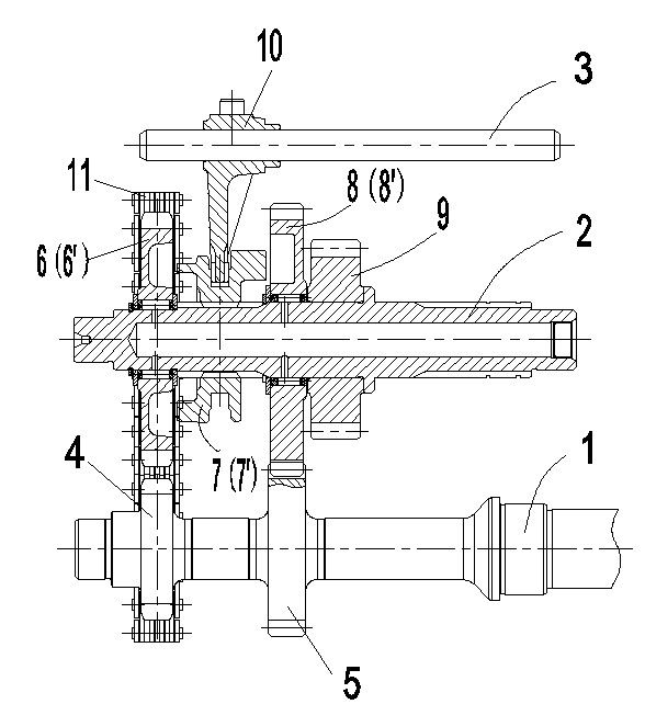
[0025] figure 1 The gear shifting mechanism of the engine shown is composed of a main shaft 1, a countershaft 2, a fork shaft 3, a reverse gear driving sprocket 4, an advancing gear driving gear 5, a driven sprocket 6, a dial wheel 7, and an advancing driven gear 8 , Output gear 9, shift fork 10 and chain 11 are formed. Reverse gear driving sprocket 4 and forward gear driving gear 5 are installed on the main shaft 1, reverse gear driven sprocket 6, thumb wheel 7, forward gear driven gear 8 and output gear 9 are installed on the countershaft 2, gear shift dial The fork 10 is installed on the shift fork shaft 3, the reverse gear driving sprocket 4 and the reverse gear driven sprocket 6 are driven by the chain 11, the forward gear driving gear 5 and the forward gear driven gear 8 are meshed for transmission, and the dial 7 is located in the reverse gear Betwee...


PUM


Abstract

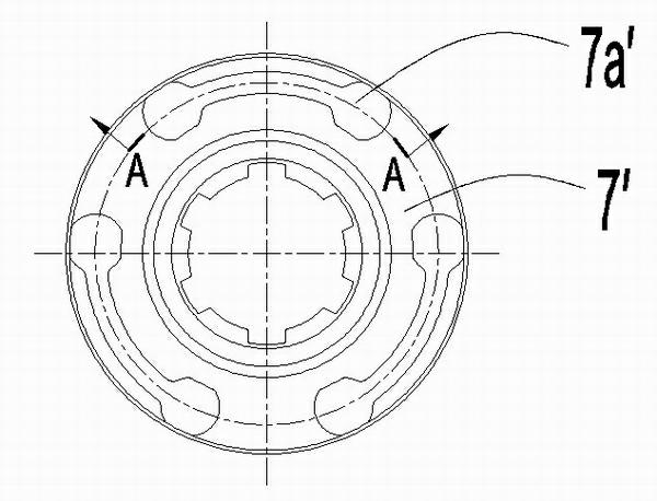
The invention discloses an engine shifting mechanism which comprises a main shaft (1), an auxiliary shaft (2) and a shifting fork shaft (3), wherein the auxiliary shaft (2) is provided with a reverse gear driven sprocket (6), a dial wheel (7) and a forward gear driven sprocket (8); first inverted cone dial claws (7a) are uniformly arranged at the periphery of the left side of the dial wheel (7) and correspond to first inverted cone dial grooves (6a) in shape which are uniformly arranged at the periphery of the right side of the reverse gear driven sprocket (6); second inverted cone dial claws (7b) are uniformly arranged at the periphery of the right side of the dial wheel (7) and correspond to second inverted cone dial grooves (8a) which are uniformly arranged at the periphery of the left side of the forward gear driven sprocket (8); one of working surfaces of the first dial claws (7a) and the second dial claws (7a) is sunk at one end close to the end surface so as to form a step (7c). In the engine shifting mechanism, the inverted cone dial claws and the inverted cone dial grooves are creatively adopted for cooperation in work, thereby limitedly avoiding the phenomena of off-gear and gear engaging slippage when the engine load is larger, and furthermore, gaps among the working surfaces of the pusher dogs and the dial grooves are appropriately designed, thereby avoiding the problem of the difficult forward gear and impact abnormal sound.

Description

technical field [0001] The invention relates to the field of motorcycle engines, in particular to a shifting mechanism used on the engine. Background technique [0002] Such as figure 1 The engine shifting mechanism shown is composed of a main shaft 1, a countershaft 2, a fork shaft 3, a reverse drive sprocket 4 arranged on the main shaft 1 and an advance drive gear 5, and a reverse gear slave arranged on the countershaft 2. Moving sprocket 6 ', thumb wheel 7 ', advancing gear driven gear 8 ' and output gear 9, the shift fork 10 that is arranged on the shift fork shaft 3, and chain 11 form. Reverse gear driving sprocket 4 and reverse gear driven sprocket 6' are transmitted through chain 11, and forward gear driving gear 5 and forward gear driven gear 8' are meshed for transmission, and dial 7' is located between reverse gear driven sprocket 6' and Between the gear driven gears 8', the shift fork 10 is inserted on the dial 7' and can drive the dial 7' to move axially. [0...

Claims


Application Information

Patent Timeline
Patent Type & Authority Applications(China)
IPC IPC(8): F16H63/30F16H63/32
Inventor 田亚平
Owner 力帆科技(集团)股份有限公司
Learn More