
Intelligent storage battery discharge energy-saving device for constant-current multi-loop feedback power grid

An energy-saving device and storage battery technology, applied to battery circuit devices, circuit devices, current collectors, etc., can solve problems such as resistance heating, energy waste, and impact on discharge accuracy, and achieve the effect of reducing energy loss

Inactive Publication Date: 2011-08-17
EAST CHINA GRID +2
View PDF2 Cites 15 Cited by
  • Summary
  • Abstract
  • Description
  • Claims
  • Application Information

AI Technical Summary

Problems solved by technology

[0006] (1) Energy waste
The energy discharged by the battery is converted into heat energy and consumed on the resistance, and the discharged energy cannot be effectively utilized
[0007] (2) The heat treatment of resistance is cumbersome
The resistor is seriously heated during the discharge process, and the handling is cumbersome
[0008] (3) The discharge accuracy is not high
The discharge current of the battery is controlled by a relay, and the current control is adjusted in steps, which affects the discharge accuracy
[0009] (4) The battery pack is separated from the system, which may easily cause interruption of output due to mains UPS, increasing the risk of system power failure
[0010] (5) Lack of protective measures

Method used


Image

  • Intelligent storage battery discharge energy-saving device for constant-current multi-loop feedback power grid
  • Intelligent storage battery discharge energy-saving device for constant-current multi-loop feedback power grid
  • Intelligent storage battery discharge energy-saving device for constant-current multi-loop feedback power grid

Examples


Embodiment Construction

[0042] The present invention will be further described below in conjunction with the accompanying drawings and embodiments.

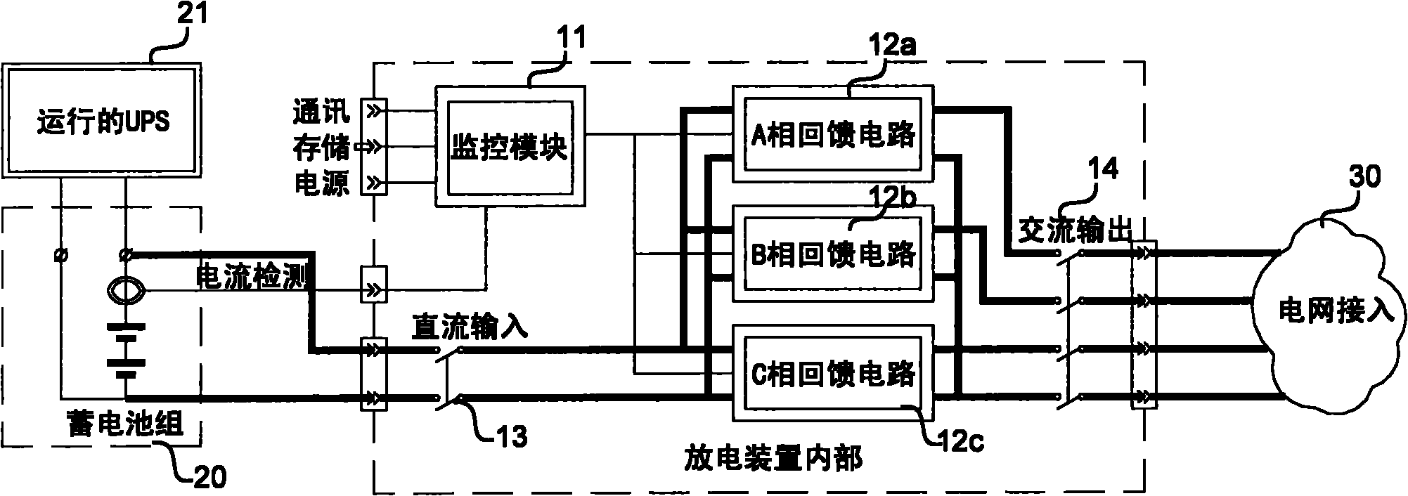
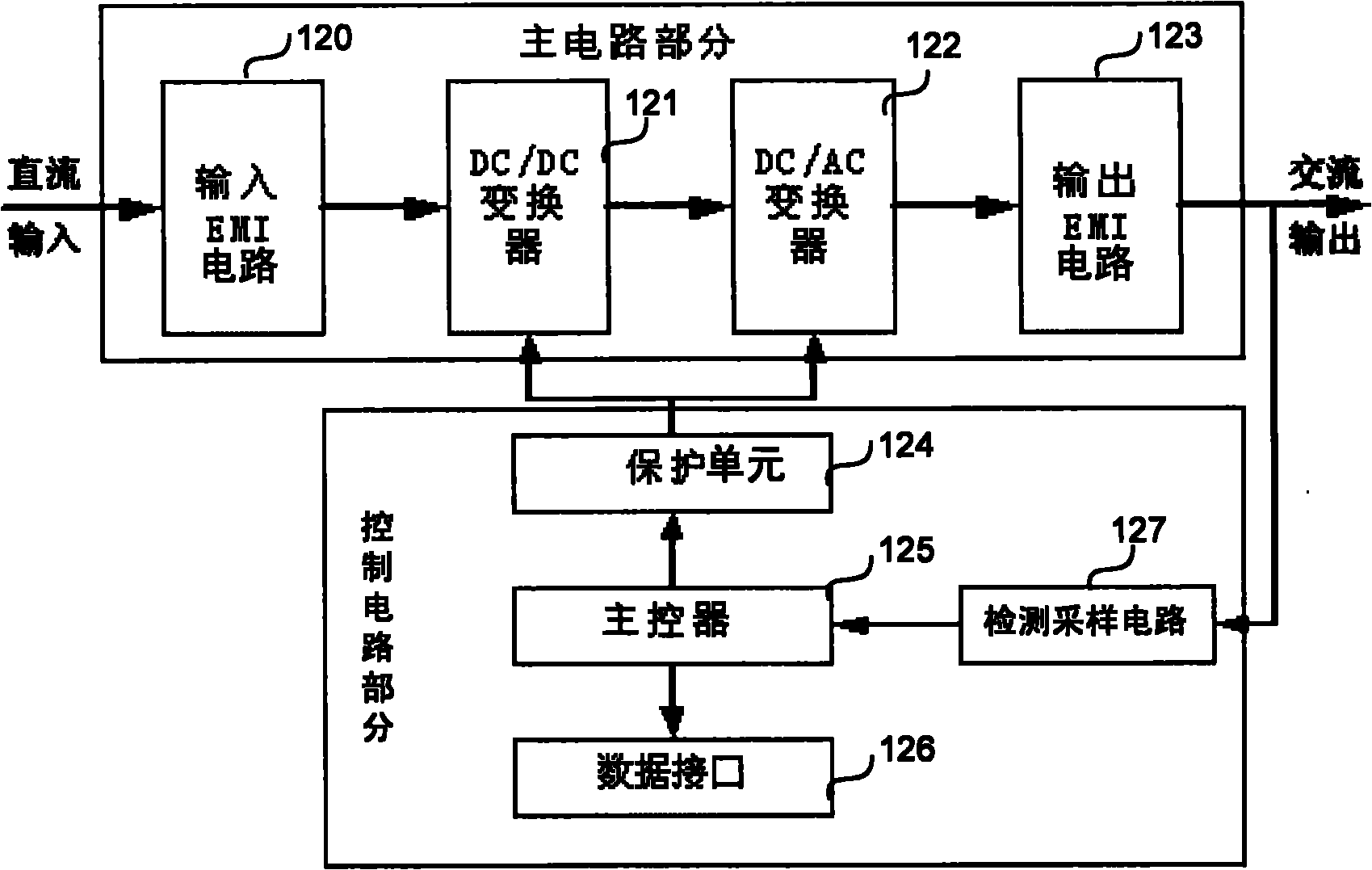
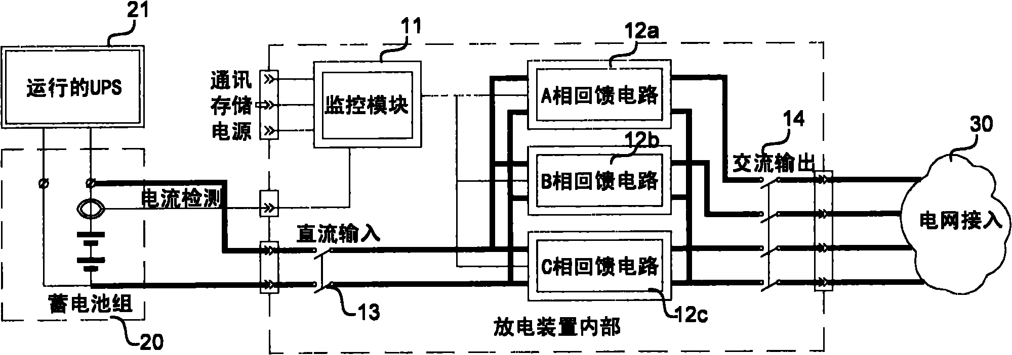
[0043] figure 1 It shows the principle of the embodiment of the constant current multi-loop feedback grid storage battery intelligent discharge energy-saving device of the present invention. See figure 1 , the constant current multi-loop feedback grid storage battery intelligent discharge energy-saving device in this embodiment includes a monitoring module 11, a DC input loop including a DC input switch 13, an AC output loop including an AC output switch 14, and a discharge feedback module. The discharge feedback module is formed by connecting multiple discharge feedback circuits in parallel, and its quantity is not limited. 12c) connected in parallel.

[0044] The connection relationship between these modules is as follows: the input end of the monitoring module 11 is connected to the battery pack 20 through the circuit detection line, and the batte...


PUM


Abstract

The invention discloses an intelligent storage battery discharge energy-saving device for a constant-current multi-loop feedback power grid, which greatly reduces energy loss and meets the national energy saving and emission reduction policy by feeding the energy in a storage battery back to a power grid by utilizing an electric energy feedback control technology instead of a conventional heating-mode discharge method. The technical scheme is that: a device comprises a monitoring module, a direct current input loop, an alternating current output loop and a discharge feedback module, wherein the input end of the monitoring module is connected with a storage battery pack through a current detection line and calculates a practical discharge current according to a detected storage battery current; the direct current input loop comprises a direct current input switch; the input end of the direct current input switch is connected with the storage battery pack; the alternating current output loop comprises an alternating current output switch; the output end of the alternating current switch is connected with the power grid; the input end of the discharge feedback module is connected with the output end of the direct current input switch; the output end of the discharge feedback module is connected with the input end of the alternating current output switch; and the direct current discharged from a storage battery is converted into a sinusoidal alternating current by means of active inversion and is fed back to the power grid.

Description

technical field [0001] The invention relates to a device for grid-connected feedback discharge of storage batteries, in particular to a device for feeding back the discharge energy of storage batteries to the grid by using sine wave grid-connected feedback control technology. Background technique [0002] The battery is an important part of UPS uninterrupted power supply, its quality is directly related to the reliability of the entire UPS system, but the battery is the device with the shortest mean time between failures in the entire UPS system. Judging from a large number of operating examples, improper use and maintenance of the battery will cause the capacity of the battery pack to be much lower than the nominal capacity after short-term use, resulting in a significantly shortened UPS uninterrupted power supply time. Regular balance charge and discharge maintenance of the battery is one of the essential means to prolong the service life of the battery and ensure the norm...

Claims


Application Information

Patent Timeline
Patent Type & Authority Applications(China)
IPC IPC(8): H02J3/38H02J7/00
Inventor 周建国徐光昶谢海宁周新雅黄捷王泽环周健潘爱强
Owner EAST CHINA GRID
Learn More