
On-line charge-discharge control and capacity verification system and method of storage battery

A charge and discharge control and battery technology, applied in the field of DC systems, can solve the problems of inability to guarantee the safety of charge and discharge process, high cost of online discharge, and insufficient accuracy of capacity estimation, so as to realize online discharge check capacity, reduce workload, The effect of reducing the renovation cost

Active Publication Date: 2017-11-17
GUANGZHOU HONGHUAI ENERGY TECH CO LTD
View PDF5 Cites 7 Cited by
  • Summary
  • Abstract
  • Description
  • Claims
  • Application Information

AI Technical Summary

Problems solved by technology

[0005] The purpose of the present invention is to overcome the deficiencies of the prior art and provide a method that can solve the problems of time-consuming and labor-intensive on-site discharge maintenance for maintenance personnel, high cost of other online discharge implementations, manual intervention charging after battery discharge, and manual reduction of rectifier output leading to battery discharge to the load. The on-line charge and discharge control and capacity check system of the storage battery can not guarantee the safety of the charge and discharge process due to the insufficient capacity estimation accuracy brought by this capacity check method.

Method used


Image

  • On-line charge-discharge control and capacity verification system and method of storage battery
  • On-line charge-discharge control and capacity verification system and method of storage battery
  • On-line charge-discharge control and capacity verification system and method of storage battery

Examples


Embodiment 1

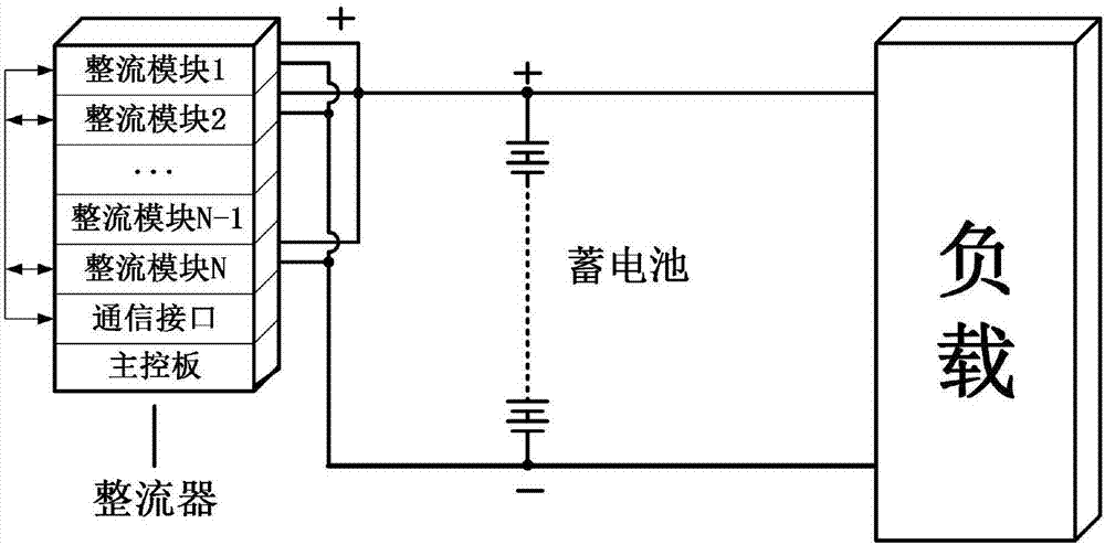
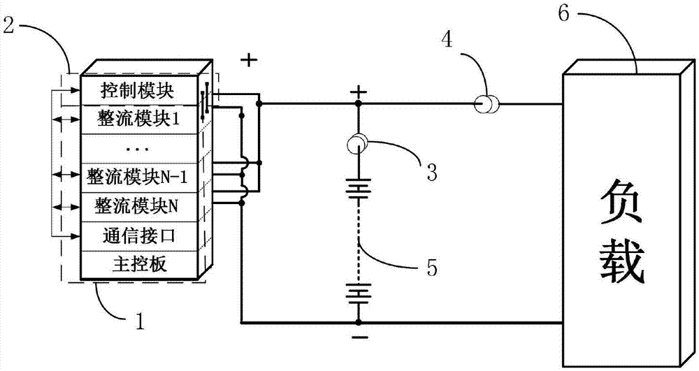
[0032] Embodiment one: see attached Figures 2 to 4 As shown, a storage battery online charge and discharge control and capacity checking system described in this embodiment includes a rectifier 1, a control module 2, a first transformer 3, a second transformer 4, a battery 5 and a load 6; the rectifier 1 includes N rectifier modules, communication interfaces and main control boards; the control module 2 includes a communication unit 2-2, an external current acquisition unit 2-3, and a CPU2-2 connected to the communication unit 2-2 and the external current acquisition unit 2-3, respectively. 1;

[0033] Wherein, the two ends of the load 6 are respectively connected with the two ends of the storage battery 5 to form a main circuit; the control module 2 is connected with the rectifier 1 through the communication unit 2-2, and is used to adjust the output voltage and output power of the rectifier 1, while the control module 2 and The rectifier 1 is connected in parallel with the...

Embodiment 2

[0039] Embodiment two: see attached figure 2 and Figure 5 As shown, it differs from Embodiment 1 in that the control module 2 includes a CPU2-1, an external current acquisition unit 2-3 connected to the CPU2-1, a PWM control circuit 2-4, and a connection between the PWM control circuit 2-4 and the CPU2- The driving circuit 2-5 of 1, the input voltage and current acquisition unit 2-6 connected to the CPU 2-1 for collecting the input voltage and current information of the control module 2, and the output voltage and current acquisition unit for collecting the output voltage and current information of the control module 2 2-7; The rectifier 1 and the control module 2 are connected in series to the DC bus, the output of the rectifier 1 is set in the battery floating charge state, and the constant current of the battery 5 is realized through the PWM control circuit of the control module and the closed-loop PWM control technology Discharge.

[0040] The specific control process ...

Embodiment 3

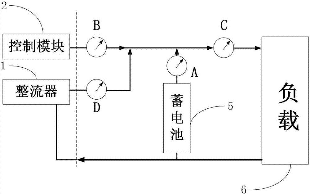
[0044] Embodiment three: see attached figure 2 and Figure 6 As shown, it differs from Embodiment 2 in that: the system also includes a single rectifier module 7; the single rectifier module 7 is connected in parallel with the rectifier 1 to the DC bus after being connected in series with the control module 2. During the discharge process, the current C of the load 6 is equal to the sum of the output current B of the control module 2, the output current D of the rectifier 1, and the discharge current A of the battery 5; during the charging process, the sum of the output current D of the rectifier 1 and the output current B of the control module 2 is equal to the sum of the output current B of the battery The sum of the charging current A and the load current C of 5.

[0045] The control module 2 makes the output voltage of the rectifier 1 slightly greater than the discharge cut-off voltage of the battery 5 through the communication unit 2-2, so that even if any abnormality o...


PUM


Abstract

The invention relates to an on-line charge-discharge control and capacity verification system and method of a storage battery. The system comprises a rectifier, a control module, a first mutual inductor, a second mutual inductor, a storage battery and a load. The two ends of the load are respectively connected with two ends of the storage battery to form a main circuit. The control module connected with the rectifier is used for regulating the output voltage and output power of the rectifier; and the control module and the rectifier are connected in parallel with the storage and the parallel unit is connected in series with the load. The first mutual inductor and the second mutual inductor respectively connected with the storage battery and the load collect current values of the storage battery and the load and send the collected current values to the control module. According to the invention, the control module regulates the output voltage and output power of the rectifier to realize constant-current charging and discharging of the storage battery; the load is capable of outputting powers continuously while any abnormity occurs during the discharging process of the storage battery; and the discharge costs are low and the operation becomes safe and reliable.

Description

technical field [0001] The invention relates to the technical field of direct current systems, in particular to an on-line charging and discharging control and capacity checking system and method for storage batteries. Background technique [0002] Battery maintenance has always been the focus and difficulty of DC system maintenance. There are many power failure accidents or communication interruption accidents caused by battery failure. Due to the complexity and invisibility of the internal performance of the battery, so far, in addition to the discharge test, it is difficult to have another method to conduct a comprehensive qualitative and quantitative test on the performance of the battery. According to the current maintenance regulations for battery packs, the battery pack must be checked and discharged every 1 or 2 years, using a nominal capacity of 0.1A for discharge to check whether its capacity reaches more than 80% of the nominal capacity. Dozens of hours are neede...

Claims


Application Information

Patent Timeline
Patent Type & Authority Applications(China)
IPC IPC(8): H02J7/00
CPCH02J7/0013H02J7/0063Y02E60/10
Inventor 张丹黄尚南黄锦燕
Owner GUANGZHOU HONGHUAI ENERGY TECH CO LTD
Learn More