
Structure box of satellite-carried electronic system for micro/nano satellite

A micro-nano satellite and electronic technology, applied in rack/frame structure, electrical equipment casing/cabinet/drawer, electrical components, etc., can solve the problems of increasing the volume and quality of the system structure, signal attenuation, low integration, etc., to achieve It is convenient for installation and system debugging, prevents left and right movement, and has the effect of simple and firm connection

Inactive Publication Date: 2014-02-26
BEIHANG UNIV
View PDF3 Cites 0 Cited by
  • Summary
  • Abstract
  • Description
  • Claims
  • Application Information

AI Technical Summary

Problems solved by technology

Each subsystem is installed in different locations, and the degree of integration is not high
There are many deficiencies in this design. The system is installed in different positions, so the design and installation are very complicated, and it is not easy to install and disassemble the system or components; Transmission requires a transmission cable, which is likely to cause signal attenuation and loss
The distributed design of the electronic system increases the volume and quality of the system structure; in addition, in some current structures, the circuit board of each system is placed in a small box, and the small boxes are connected by cables, so that the installation of the system will be convenient. However, a lot of cables are still needed, which takes up a lot of space on the satellite, which is not conducive to the integration of small satellites; due to the above defects, the existing electronic system structure on the satellite has a large footprint, low integration, requires a lot of cables, and is inconvenient to install. and other shortcomings

Method used


Image

  • Structure box of satellite-carried electronic system for micro/nano satellite
  • Structure box of satellite-carried electronic system for micro/nano satellite
  • Structure box of satellite-carried electronic system for micro/nano satellite

Examples


Embodiment Construction

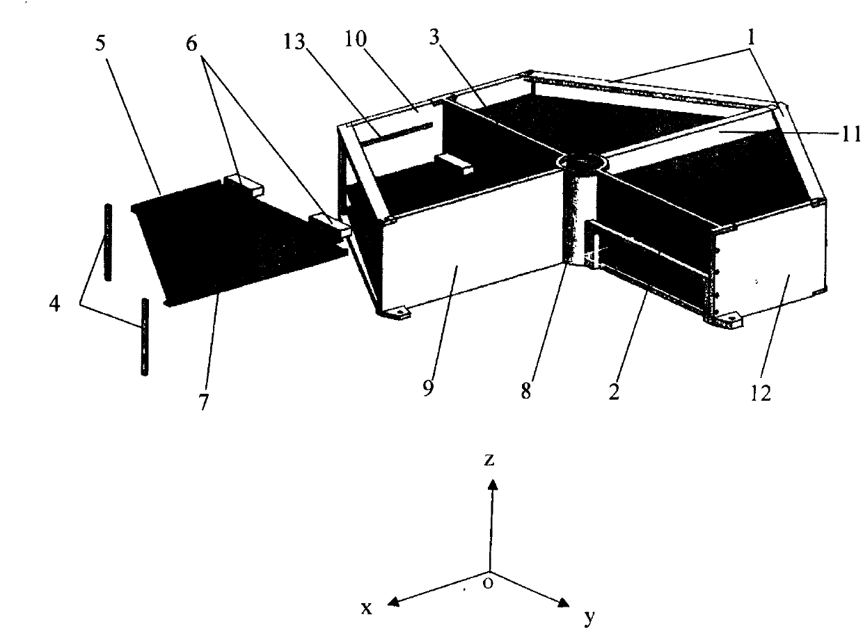
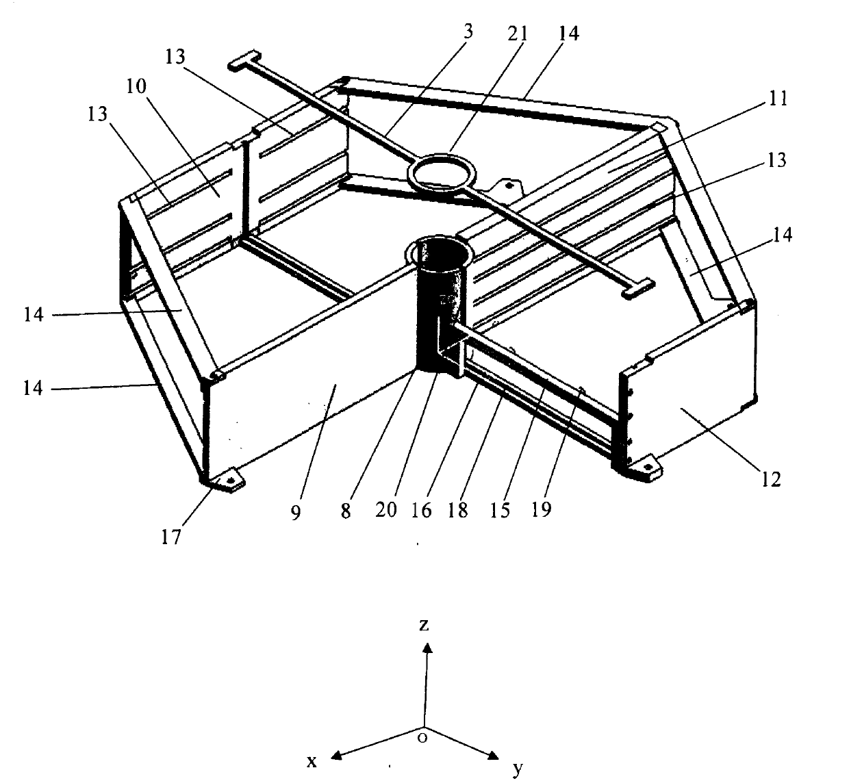
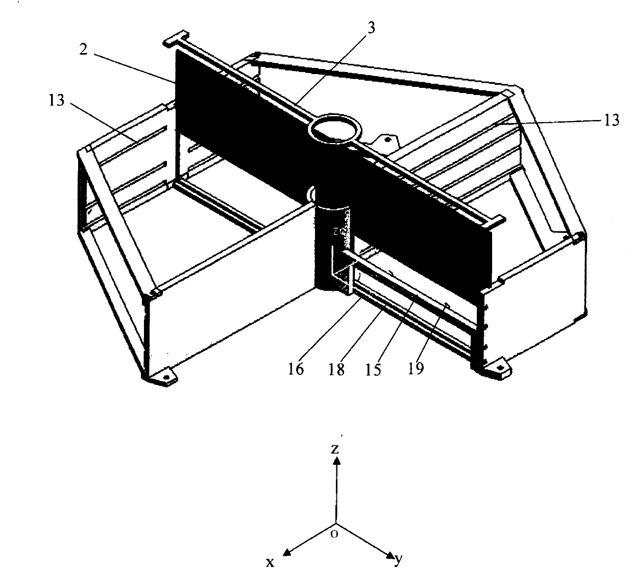
[0017] The overall installation diagram of a structural box for electronics on a micro-nano-satellite satellite of the present invention is as follows figure 1 , according to the shape of the hexagonal prism of the micro-nano-satellite, in order to match the shape of the micro-nano-satellite, the electronic structural box on the micro-nano-satellite is also designed as a hexagonal prism, as shown in figure 1 As shown in , one of the vacated corners is used to install the battery on the satellite. The electronic structural box on the micro-nano satellite includes a structural frame 1, a back plate 2, a back plate locking bar 3, a board card locking bar 4, an "L"-shaped guide rail 5, and a CPCI connector 6. The backboard 2 is installed in the structural frame 1 through the backboard mounting guide groove and the slits on both sides of the central column 8 , and the top of the backboard 2 cooperates with the guide groove on the backboard locking bar 3 to install and lock the back...


PUM


Abstract

The invention provides a structure box of a satellite-carried electronic system for a micro / nano satellite, which comprises a structure frame, a back board, a back board fastening bar, a board card fastening bar and a CPCI (Compact Peripheral Component Interconnect) connector. The back board is arranged in the structure frame through back board mounting guide grooves and seams on two sides of a center column, and the back board is fastened by arranging the top of the back board and guide grooves on the back board fastening bar in a matching manner. L-shaped guide rails are arranged on two sides of a circuit board card, the L-shaped guide rails are arranged in the frame through L-shaped guide grooves on the structure frame, and the circuit board card is fastened by using the board card fastening bar. The board card fastening bar is arranged on the structure frame. The circuit board card and the back board are connected through the CPCI connector. The invention has the advantages of realizing electric distributed and structural integration of the satellite-carried electronic system for the micro / nano satellite, reducing the volume and the weight, being convenient to arrange and debug, and being suitable for satellite-carried electronic systems for micro and nano types satellites.

Description

technical field [0001] The invention relates to a structural box for electronics on a micro-nano satellite, which belongs to the field of aircraft design. Background technique [0002] With the development and application of information technology and integrated technology, the traditional satellite development technology has undergone a revolutionary leap. The functions of satellites that originally required several tons or even dozens of tons can now be used for tiny satellites that weigh hundreds of kilograms or even tens of kilograms. To achieve, so that new vitality appeared in the field of aerospace and space applications. Microsatellites have the advantages of light weight, small size, low cost, short development cycle, and convenient launch. They are playing an increasingly important role in many fields such as deep space exploration, communications, military applications, remote sensing, weather forecasts, and scientific experiments. . [0003] The traditional sat...

Claims


Application Information

Patent Timeline
Patent Type & Authority Patents(China)
IPC IPC(8): H05K5/00H05K7/18
Inventor 袁春柱朱庄生韩潮郭雷马静
Owner BEIHANG UNIV
Learn More