Elevator car lighting device

A lighting device and car technology, which is applied to elevators, transportation and packaging in buildings, can solve problems such as dirt, and achieve the effects of reducing pressure, reducing the size of the protrusion, and reducing the frequency of cleaning

Active Publication Date: 2011-08-24
HITACHI BUILDING SYST CO LTD
View PDF11 Cites 10 Cited by
  • Summary
  • Abstract
  • Description
  • Claims
  • Application Information

AI Technical Summary

Problems solved by technology

Therefore, the light-receiving surface of the light-transmitting plate that receives the light emitted from the light-emitting element is easily dirty due to the dust that enters between the light-emitting plate and the light-transmitting plate, so the light-receiving surface needs to be cleaned frequently
In addition, for the car lighting device of the prior art, since it protrudes into the car, it will give passengers a sense of oppression.

Method used


Image

  • Elevator car lighting device
  • Elevator car lighting device
  • Elevator car lighting device

Examples


no. 1 Embodiment approach

[0028] Refer below Figure 1 to Figure 4 The car lighting device of the first embodiment will be described.

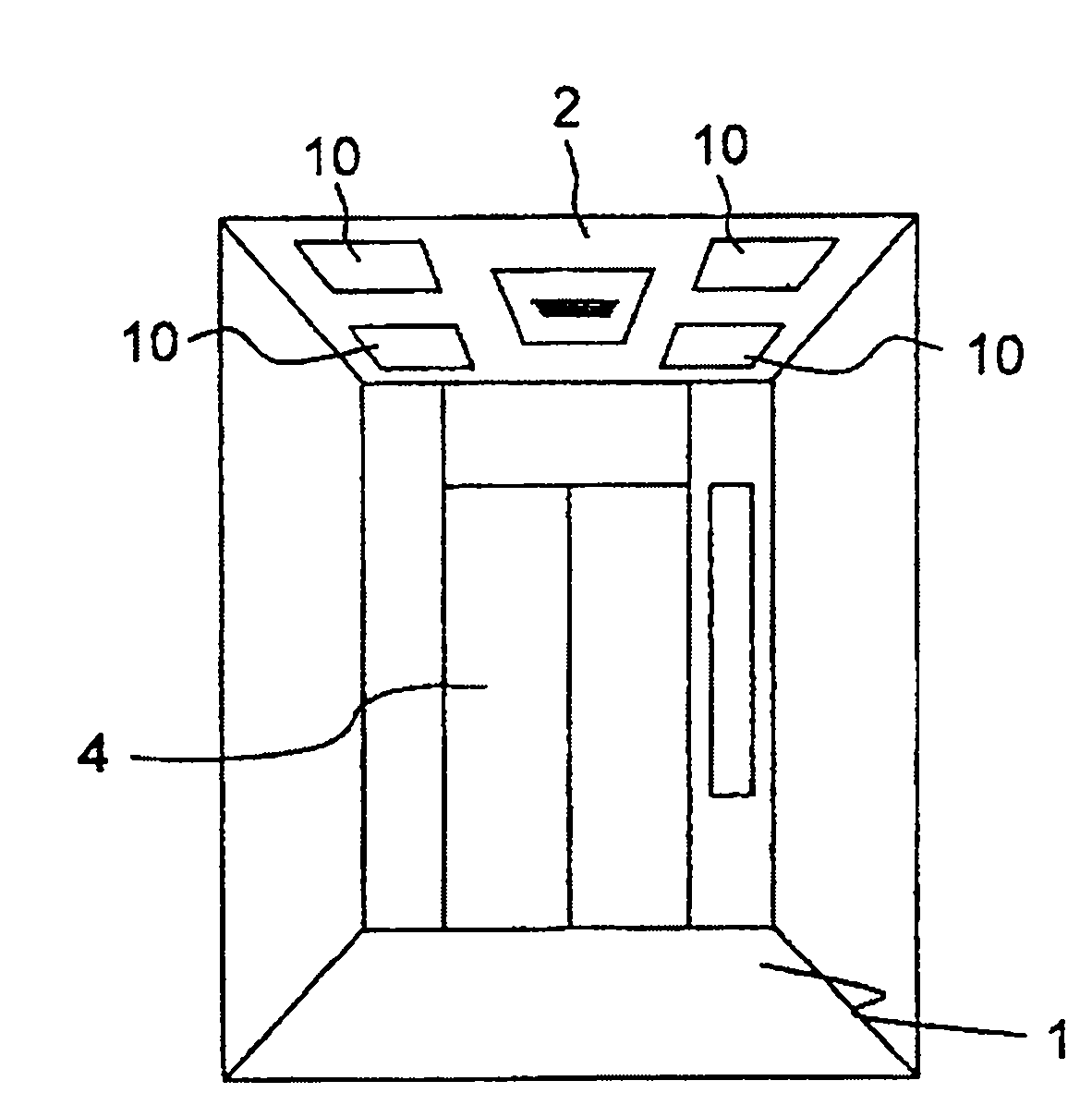
[0029] Such as figure 1 As shown, the roof of the car 1 of the elevator is formed by a ceiling 2 . Four car lighting devices 10 of the first embodiment are provided on the ceiling 2 . figure 1 4 in is the car door.

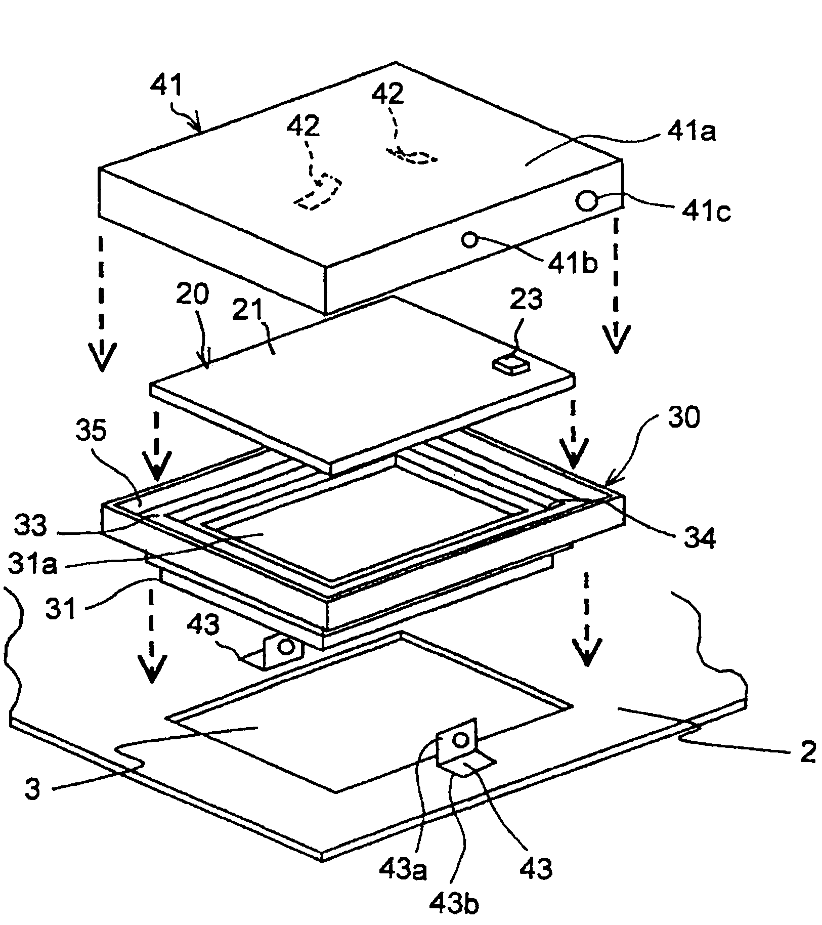
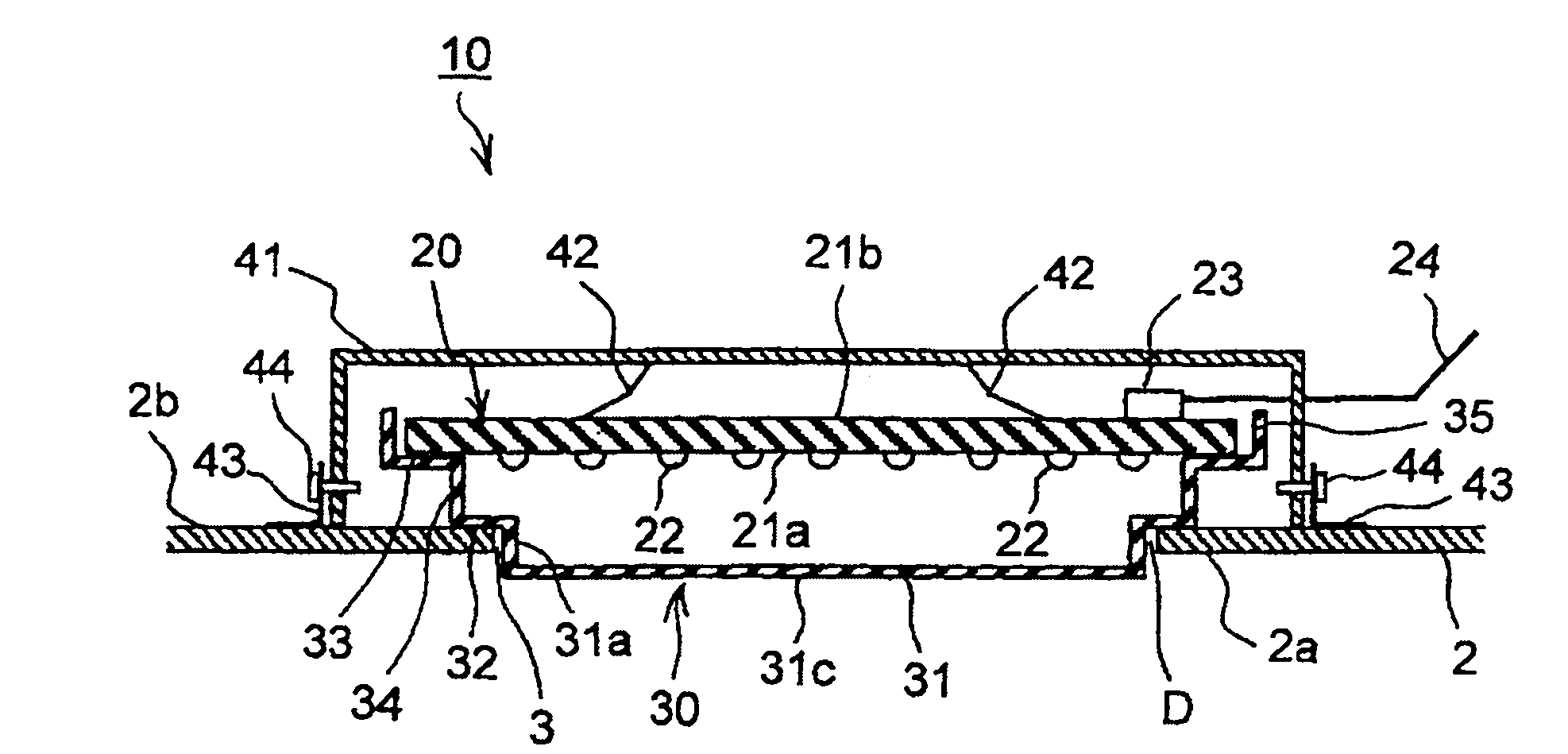
[0030] Such as figure 2 , image 3 As shown, the car lighting device 10 includes: a ceiling 2 forming the ceiling of the car 1; LED22 as a light-emitting element (refer to image 3 ) light emitting board 20;

[0031] The light-emitting panel 20 has a substrate 21 that is a rectangular plate member that is deployed along a direction substantially parallel to the direction in which the ceiling 2 is deployed. A plurality of LEDs 22 are arranged on the lower surface 21a (the surface on the car 1 side) of the substrate 21 . The intervals between adjacent LEDs 22 are constant, and they are evenly distributed in dots over substantially the entire surfa...

no. 2 approach

[0055] Refer below Image 6 A car lighting device according to a second embodiment will be described.

[0056] Such as Image 6 As shown, the car lighting device 200 of the second embodiment has a light-transmitting plate 201 having a shape different from that of the light-transmitting plate 30 of the first embodiment. The surface emission performance of the transparent plate 201 is the same as that of the transparent plate 30 . The structure of the car lighting device 200 other than the light-transmitting plate 201 is the same as that of the car lighting device 10 .

[0057] The light-transmitting plate 201 of the car lighting device 200 does not have the partition part 34 like the light-transmitting plate 30 of the car lighting device 10 . In addition, the plate thickness of the light-transmitting plate 201 can be regarded as having the function of the spacer, but in the second embodiment, the function of the spacer due to the plate thickness is not substantial, so in the...


PUM


Abstract

The invention provides an elevator car lighting device capable of protecting the light receiving face of a light-passing board from being polluted by the dusts of the outside and reducing the extension dimension toward the indoor. The elevator car lighting device comprises a car ceiling, a luminescent board equipped with an LED unfolding along the direction parallel to the ceiling, a light-passing board covered the lower part of the luminescent board and a fixed mechanism for fixing the luminescent board and the light-passing board on the ceiling. The ceiling is equipped with an opening part. The light-passing board is equipped with a main body part for being inserted in the opening part, an annular shedding-proof part hung on the ceiling and arranged on the periphery of the opening part and an annular support part arranged above the shedding-proof part for supporting the edge of the luminescent board. When the edge of the luminescent board is supported by the support part, the luminescent board is positioned to block the recess part.

Description

technical field [0001] The present invention relates to an elevator car lighting device that uses a plurality of light emitting elements arranged on a substrate as a light source to illuminate the inside of an elevator car. Background technique [0002] In the prior art, a car lighting device for illuminating the interior of the elevator car is usually installed on the roof of the elevator car. The lighting device for the car includes: a reinforcing plate mounted on the underside (surface of the side side of the car) of the ceiling constituting the car roof of the elevator car; a light-emitting plate installed under the reinforcing plate and provided with a light-emitting element; A light-transmitting plate arranged to cover the light-emitting element is installed under the light-emitting plate through a support. Between the light-emitting plate and the light-transmitting plate, there is a gap corresponding to the length of the pillar. In the elevator car lighting device t...

Claims


Application Information

Patent Timeline
Patent Type & Authority Applications(China)
IPC IPC(8): B66B11/02
Inventor 弦间康仁花冈义泰
Owner HITACHI BUILDING SYST CO LTD
Why Eureka
Try Eureka