
Micro projection device

一种微型投影、设备的技术,应用在投影显示领域,能够解决投影设备无法正常使用、影响画面显示质量、不利微型投影设备等问题

Active Publication Date: 2015-07-22
BEIJING PICO TECH
View PDF6 Cites 32 Cited by
  • Summary
  • Abstract
  • Description
  • Claims
  • Application Information

AI Technical Summary

Problems solved by technology

Since the optical display system is very sensitive to dust, as long as it is polluted, the display quality of the picture will be affected, and when the pollution reaches a certain level, it will directly cause the projection equipment to fail to work normally. Therefore, the dustproof design of the micro projection equipment is very important
However, the micro-projection device is still in the rough stage of development, and the dust-proof design basically stays at the stage of sealing the outer cover to encapsulate the optical display system in the outer cover. This kind of dust-proof structure is not conducive to the micro-projection device. The heat dissipation design of the openings on the cover, the diopter adjustment design, the interpupillary distance adjustment design, etc. Therefore, in order to adapt to the further development of micro-projection equipment, it is urgent to provide a higher-level dust-proof structure with unrestricted openings in the cover

Method used


Image

  • Micro projection device
  • Micro projection device
  • Micro projection device

Examples


Embodiment 1

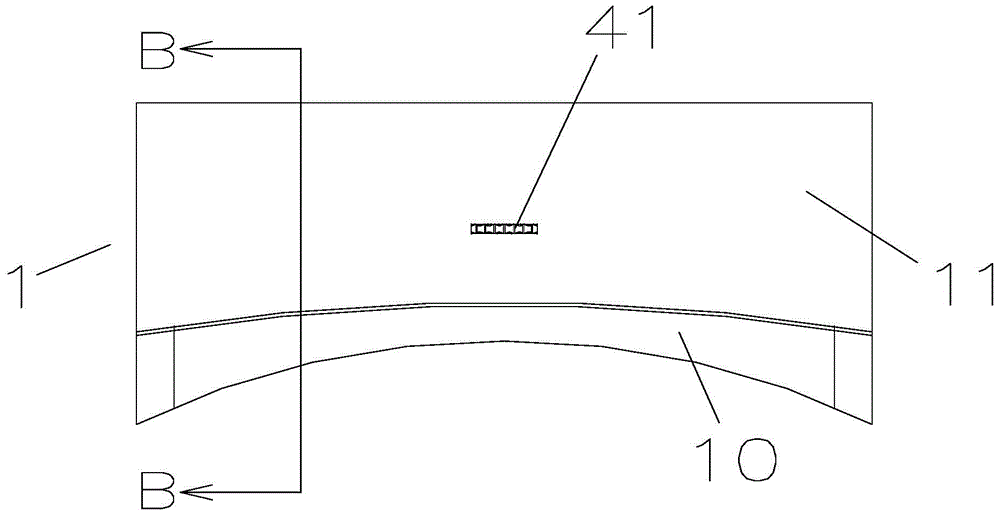
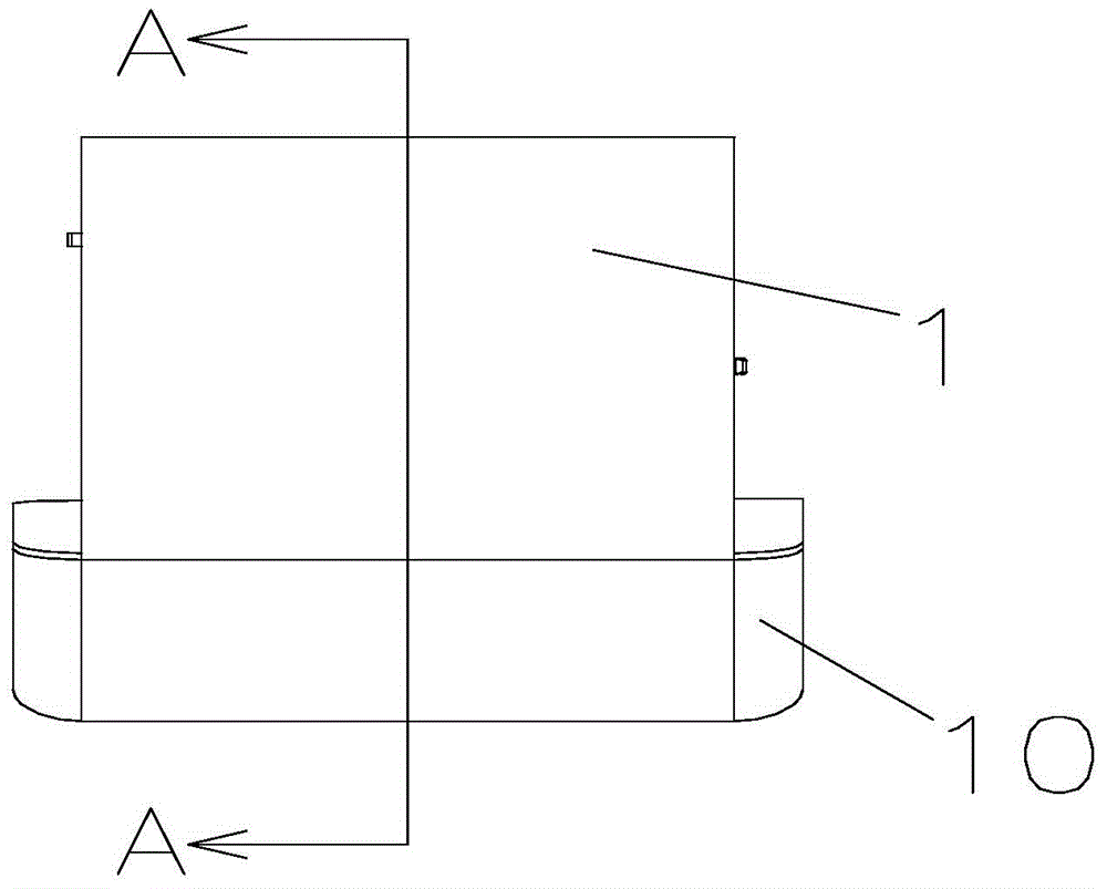
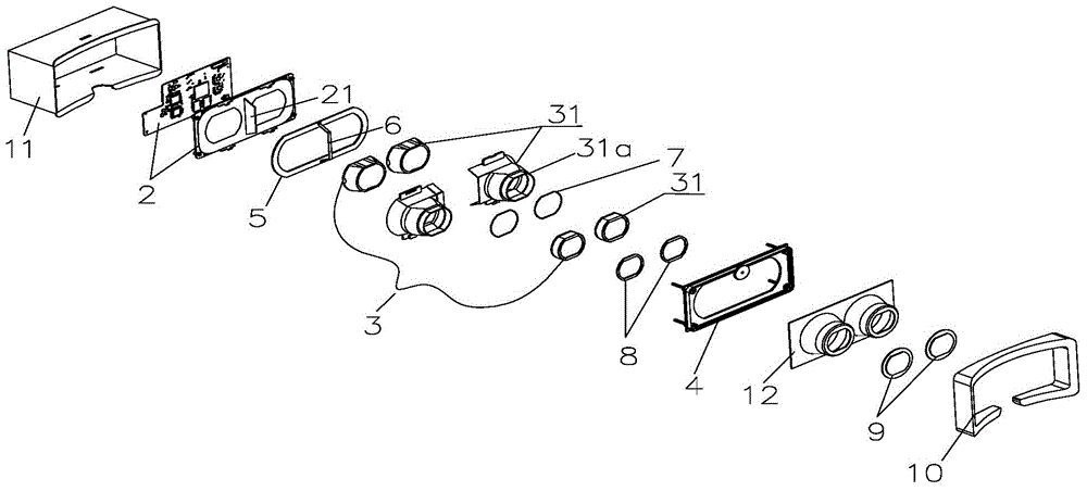
[0038] The above-mentioned lens module 3 can adopt the most basic optical structure, that is, the lens module 3 is provided with only one lens 3b, and the lens 3b is a convex lens. However, in order to realize optical design such as eliminating chromatic aberration, eliminating image distortion, and magnifying the viewing angle, the lens module 3 will include at least two lenses 3b, which can be installed in the module lens barrel 3a designed as a whole, or can be They are arranged in different separate lens barrels, so as to facilitate the assembly of the lens module 3 and facilitate the optimal diopter adjustment design. Take the optical design that eliminates chromatic aberration as an example, such as Figure 3 to Figure 6 As shown, the lens module 3 can include two lenses 3b arranged in the module lens barrel 3a, and the adjacent display module 2 is arranged as a concave lens, and adjacent to the window 9 is arranged as a convex lens, so that positive and negative can be ...

Embodiment 2

[0042] like Figure 3 to Figure 8 As shown, the micro-projection device of the present invention includes two lens modules 3, left and right, and the display module 2 has two corresponding display areas, left and right. Here, the two display areas can be realized by partitioning a display screen. It can also be realized by two display screens, and the module lens barrels 3a of the two lens modules 3 are independent of each other, so as to form the module lens barrel 3a with a closed barrel wall, and then facilitate the formation of the above-mentioned closed space. The lens 3b of the lens module 3 is encapsulated in the left closed space enclosed by the module barrel 3a of the left lens module 3, the corresponding side window 9 and the display module 2, and the left display area is located on the left side. In the closed space, the lens 3b of the right lens module 3 is encapsulated in the right closed space surrounded by the module lens barrel 3a of the right lens module 3, th...

Embodiment 3

[0045] like Figure 3 to Figure 10 As shown, the micro-projection device of the present invention includes two lens modules 3, left and right, the display module 2 has two corresponding display areas, left and right, and the display module 2 is provided with a light blocking plate between the two display areas. 21. The module lens barrels 3a of the two lens modules 3 are provided with a gap 3a1 that is adapted to the light blocking plate 21, and the gap frame 3a2 of the two lens modules Each of the module lens barrels 3a is connected to each other at the respective gap frames 3a2, and an intermediate dust pad 6 is sandwiched between the gap frames 3a2 of the two module lens barrels 3a, so as to prevent the intersection of the two module lens barrels 3a. This embodiment is equivalent to encapsulating all the lenses 3b in a closed space surrounded by the display module 2, the two viewing windows 9 and the two module lens barrels 3a that penetrate each other, and the two display ...


PUM


Abstract

The invention discloses a micro projection device comprising an outer cover (1) and a display module (2) and lens modules (3) both mounted in the outer cover (1). Each lens module (3) comprises a module lens barrel (3a) and a lens (3b) mounted in the module lens barrel (3a); a front dustproof pad (5) is clamped between a front open edge (3c) of each module lens barrel (3a) and a display region frame of the display module (2), and a rear dustproof pad (8) is clamped between a rear open edge (3d) of each module lens barrel (3a) and a window (9) in the outer cover (1), so that the lens (3b) are packaged in an enclosed space circled by the module lens barrels (3a), the window (9) and the display module (2), and the display region of the display module (2) is located in the enclosed space. The dustproof structure of the micro projection device has high dustproof level and is unaffected by the design of various openings in the outer cover.

Description

technical field [0001] The present invention relates to the technical field of projection display, in particular to a dustproof structure of a micro-projection device. Background technique [0002] Micro projection equipment, also known as portable projection equipment or pocket projection equipment, as a device for displaying images and colors, the core structure is an optical display system including a display module and a lens module. Since the optical display system is very sensitive to dust, as long as it is polluted, it will affect the display quality of the picture, and when the pollution reaches a certain level, it will directly cause the projection equipment to fail to work normally. Therefore, the dustproof design of the micro-projection equipment is very important. However, the micro-projection equipment is still in the rough stage of development, and the dust-proof design is still basically at the stage of sealing the outer cover to encapsulate the optical displa...

Claims


Application Information

Patent Timeline
Patent Type & Authority Applications(China)
IPC IPC(8): G03B21/14
CPCG03B21/145G02B7/12G02B27/0006G02B27/017G02B2027/0154G02B27/0172G02B27/0176
Inventor 张锋
Owner BEIJING PICO TECH
Learn More