LED photographic lamp capable of changing illumination angle

A technology of LED video light and illumination angle, which is applied to the parts, photography, refractors and other directions of lighting devices, can solve the problems of inconsistent brightness, uneven light edges, affecting light quality, etc., to achieve consistent light intensity, uniform and soft light source , the effect of convenient change

Inactive Publication Date: 2011-08-24
FUZHOU F&V PHOTOGRAPHIC EQUIP
View PDF10 Cites 0 Cited by
  • Summary
  • Abstract
  • Description
  • Claims
  • Application Information

AI Technical Summary

Problems solved by technology

[0002] Most of the existing LED video lights cannot change the illumination angle. Although a very small number of LED video lights can change the illumination angle, they cannot obtain the required illumination angle accurately, quickly and conveniently without affecting the light quality.
[0003] The existing LED video lights that can change the irradiation angle generally adopt the following two methods: 1. Use a four-leaf light baffle to limit the irradiation range of the video light to control the illumination angle of the video light. Its shortcoming is: it can only be roughly Changing the illumination angle will make the edge of the light not smooth or deformed; 2. Control the illumination angle of the whole lamp by mixing and adjusting two groups of illuminants with different illumination angles. The light can also affect the quality of the light, making the brightness of the center of the illumination inconsistent with the edge (the area illuminated by the two sets of lights together is particularly bright, while the brightness of the wider angle set of lights is inconsistent)

Method used


Image

  • LED photographic lamp capable of changing illumination angle
  • LED photographic lamp capable of changing illumination angle
  • LED photographic lamp capable of changing illumination angle

Examples


Embodiment Construction

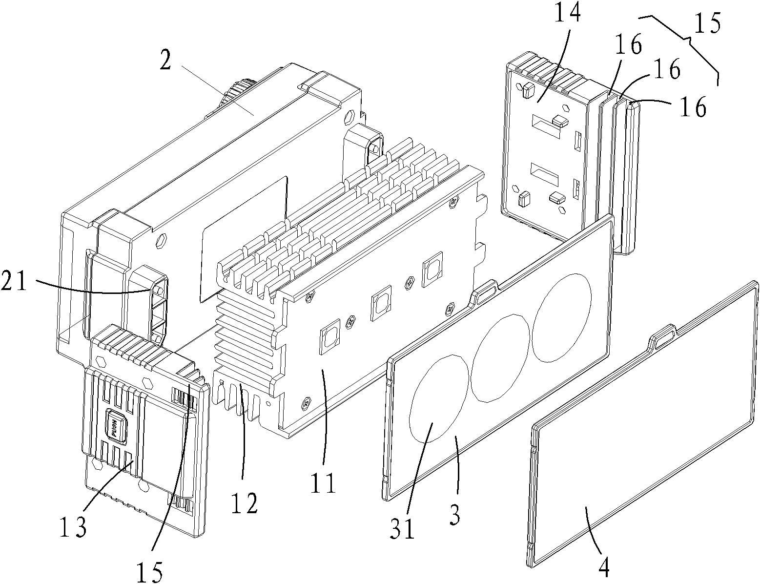
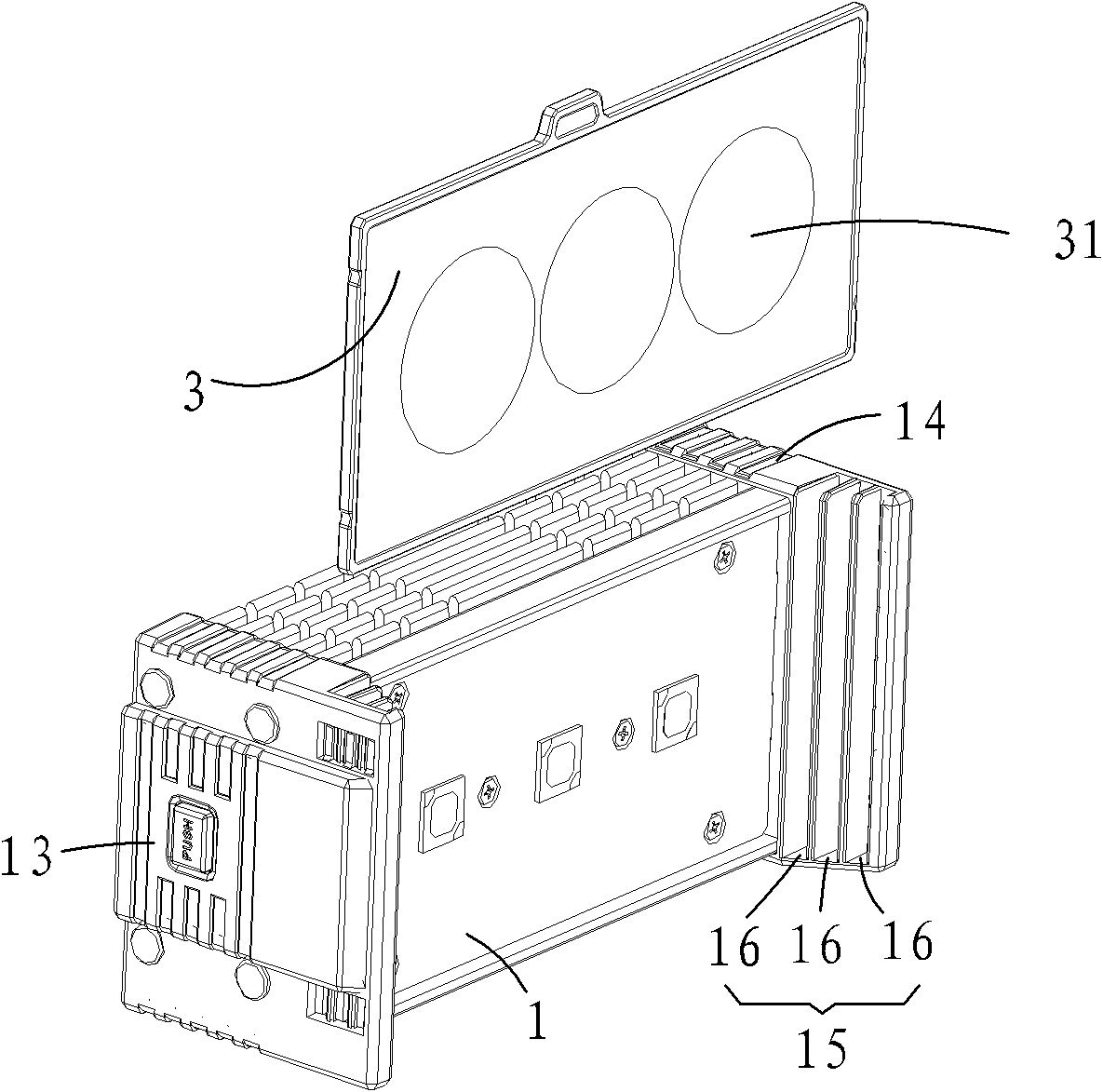
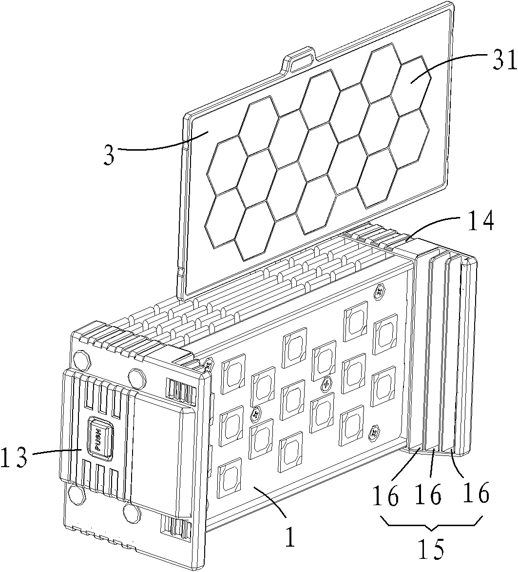
[0021] see Figure 1 to Figure 3 As shown, the embodiments of the present invention will be described in detail.

[0022] Such as figure 1 , the present invention is an LED video light that can change the irradiation angle, which includes a lamp head assembly 1 and a control box assembly 2, the lamp head assembly 1 is connected to the control box assembly 2, connected to the power supply, and the knob switch is turned to activate the light. The lamp head assembly 1 and the control box assembly 2 are detachably connected by a buckle mechanism 21 . to combine figure 2 , the lamp head assembly 1 includes: a light plate 11, a heat dissipation block 12 connected to the back of the light plate 11, and a left housing 13 connected to the light plate 11 and the left end of the heat dissipation block 12, connected to the light plate 11, The right housing 14 at the right end of the cooling block 12 . Because the lamp head assembly 1 is connected to the control box assembly 2 in a d...


PUM


Abstract

The invention provides an LED photographic lamp capable of changing an illumination angle. The LED photographic lamp comprises a lamp holder assembly and a control box assembly, wherein the lamp holder assembly is connected with the control box assembly; two notch sections are symmetrically arranged on both sides of the front end of the front light emitting surface of the lamp holder assembly; and each notch section comprises at least two notches. The LED photographic lamp also comprises an optical lens assembly, wherein the optical lens plates correspond to the notches; and both ends of the optical lens plates are respectively embedded in the two symmetrical notches. The lamp holder assembly is connected with the control box assembly in a detachable manner through a buckle mechanism. The LED photographic lamp can accurately, rapidly and conveniently change the illumination angle without influencing the light intensity and the light quality.

Description

【Technical field】 [0001] The invention relates to a light source device for photography and videography, in particular to an LED videography light. 【Background technique】 [0002] Most of the existing LED video lights cannot change the illumination angle. Although a very small number of LED video lights can change the illumination angle, they cannot obtain the required illumination angle accurately, quickly and conveniently without affecting the light quality. [0003] The existing LED video lights that can change the irradiation angle generally adopt the following two methods: 1. Use a four-leaf light baffle to limit the irradiation range of the video light to control the illumination angle of the video light. Its shortcoming is: it can only be roughly Changing the illumination angle will make the edge of the light not smooth or deformed; 2. Control the illumination angle of the whole lamp by mixing and adjusting two groups of illuminants with different illumination angles....

Claims


Application Information

Patent Timeline
Patent Type & Authority Applications(China)
IPC IPC(8): G03B15/05F21V5/04F21V13/00F21V17/00F21Y101/02F21Y115/10
Inventor 詹小明
Owner FUZHOU F&V PHOTOGRAPHIC EQUIP
Why Eureka
Try Eureka