Slow-wave structure of multiple-beam coupling cavity traveling-wave tube and manufacturing method of slow-wave structure
A slow-wave structure and manufacturing method technology, which is applied in the manufacture of discharge tubes/lamps, cold cathodes, electrode systems, etc., can solve the problem of permanent magnet focusing system failure, scrapped traveling wave tubes, and poor electron injection flow rate. and other problems, to achieve the effect of improving the pass rate, work stability, and simple and feasible operation.
- Summary
- Abstract
- Description
- Claims
- Application Information
AI Technical Summary
Problems solved by technology
Method used
Image
Examples
Embodiment 1
[0041] The manufacturing method of the multi-beam coupled cavity traveling wave tube slow wave structure includes the following steps;
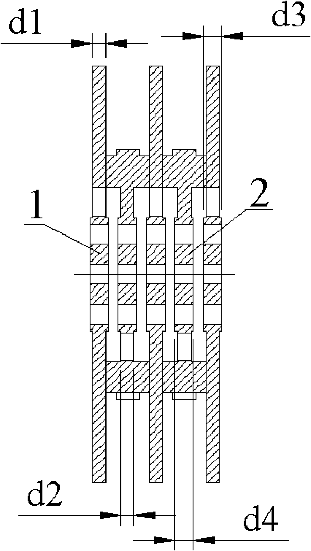
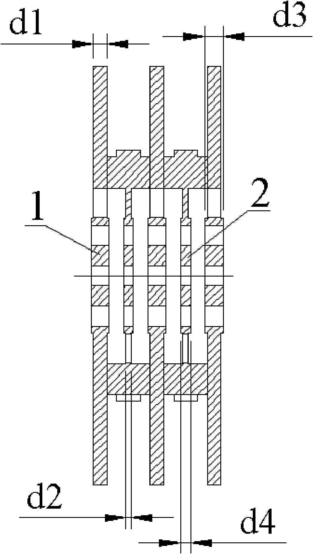
[0042] (1) Make the pole shoe and copper ring, so that the thickness d1 of the pole shoe is greater than the thickness d2 of the copper ring;
[0043] (2) Arrange the pole shoes and copper rings prepared in (1) alternately, the coupling grooves arranged on the pole shoes and copper rings are staggered and arranged at 180°, and the pole shoes and copper rings are welded by brazing Connected into a multi-beam coupler chain.
Embodiment 2
[0045] The manufacturing method of the multi-beam coupled cavity traveling wave tube slow wave structure includes the following steps;
[0046] (1) Make the pole shoe and copper ring, so that the thickness d1 of the pole shoe is greater than the thickness d2 of the copper ring; the thickness d1 of the pole shoe is 0.4 times the period L of the slow wave system of the traveling wave tube, and d1 is 1.2 mm; the thickness of the copper ring d2 is 0.3 times of the period L of the slow wave system of the traveling wave tube, and d2 is 0.9mm;
[0047] (2) Process the coupling grooves of the pole shoe and the copper ring in (2), so that the angle of the coupling groove of the pole shoe is greater than the angle of the coupling groove of the copper ring; the angle of the coupling groove on the pole shoe is 56° °, the angle of the coupling groove on the copper ring is 52.2°, so that the working frequency band of the traveling wave tube does not shift;
[0048] (3) Process the loading ...
Embodiment 3
[0052] The manufacturing method of the multi-beam coupled cavity traveling wave tube slow wave structure includes the following steps;
[0053] (1) Make the pole shoe and copper ring, so that the thickness d1 of the pole shoe is greater than the thickness d2 of the copper ring; the thickness d1 of the pole shoe is 0.5 times the period L of the slow wave system of the traveling wave tube, and d1 is 1.5 mm; the thickness of the copper ring d2 is 0.2 times of the period L of the slow wave system of the traveling wave tube, and d2 is 0.6mm;
[0054] (2) Process the coupling grooves of the pole shoe and the copper ring in (2), so that the angle of the coupling groove of the pole shoe is greater than the angle of the coupling groove of the copper ring; the angle of the coupling groove on the pole shoe is 58° °, the angle of the coupling slot on the copper ring is 50°, so that the working frequency band of the traveling wave tube does not shift;
[0055] (3) Process the loading head...
PUM
 Abstract
Description
Claims
Application Information
 - R&D
- Intellectual Property
- Life Sciences
- Materials
- Tech Scout
- Unparalleled Data Quality
- Higher Quality Content
- 60% Fewer Hallucinations
Browse by: Latest US Patents, China's latest patents, Technical Efficacy Thesaurus, Application Domain, Technology Topic, Popular Technical Reports.
© 2025 PatSnap. All rights reserved.Legal|Privacy policy|Modern Slavery Act Transparency Statement|Sitemap|About US| Contact US: help@patsnap.com


