Charger with automatic power-off function

An automatic power-off and charger technology, which is applied in current collectors, non-polar relays, battery circuit devices, etc., can solve the problems of battery failure and delay in charging time, and achieve the effects of simple structure, avoiding waste, and convenient use

Inactive Publication Date: 2011-08-24
CHANGCHUN INST OF OPTICS FINE MECHANICS & PHYSICS CHINESE ACAD OF SCI
View PDF4 Cites 17 Cited by
  • Summary
  • Abstract
  • Description
  • Claims
  • Application Information

AI Technical Summary

Problems solved by technology

The imperfection of this method is: when the charger is plugged into the power base for charging, if the operator accidentally forge

Method used


Image

  • Charger with automatic power-off function
  • Charger with automatic power-off function
  • Charger with automatic power-off function

Examples


Embodiment Construction

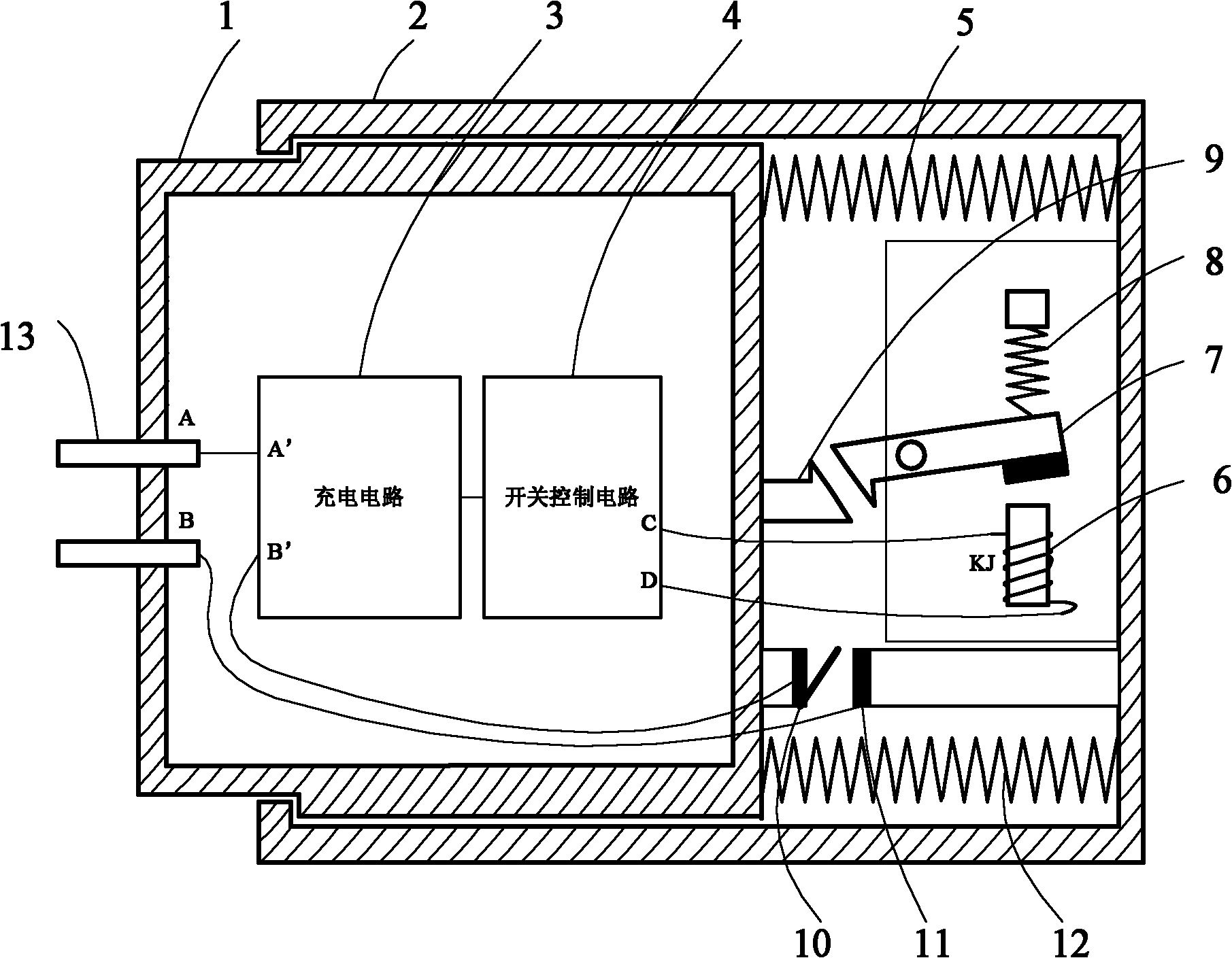
[0012] Such as figure 1 As shown, the charger with automatic power-off function of the present invention includes an inner casing 1, a plug 13, a charging circuit 3, a switch control circuit 4, an inner casing stop hook 9, a metal spring piece 10, an outer casing 2, and a pressure spring 5, 12, electromagnet 6, outer shell stop hook 7, tension spring 8, metal contact 11; plug 13 is fixed on inner shell 1; inner shell 1 and outer shell 2 are connected by compression spring 5, 12 ; The inner casing stop hook 9 and the metal spring piece 10 are fixed on the inner casing 1; the outer casing stop hook 7 is installed in the outer casing 2 through the rotating shaft 14, and the front end with the hook is in line with the position of the inner casing stop hook 9 Correspondingly, the end of the housing body stop hook 7 is connected to the housing body 2 through a tension spring 8; When the coil KJ is energized, the electromagnet 6 generates a magnetic force, and under the action of th...


PUM


Abstract

The invention relates to a charger with an automatic power-off function. When a plug is inserted into a power source socket, the charger is connected with press springs of an internal housing and an external housing; an internal housing stopping hook hooks up an external housing stopping hook; a metallic spring plate fixed on the internal housing is connected with metallic contact points fixed onthe external housing to enable a charging circuit to charge a battery; when the battery is fully charged, a switch control circuit is conducted, an electric magnet is magnetized to suck the tail end of the external housing stopping hook for separating the internal housing stopping hook from the external housing stopping hook; and simultaneously, the metallic spring plate is disconnected with the metallic contact points. When the plug is inserted into the power source socket, the charger can automatically conduct the power supply, and automatically switch off the power supply after the batteryis fully charged, so that the energy waste is avoided; and the battery is prevented from being damaged due to long-time charging.

Description

technical field [0001] The invention relates to a charger, in particular to a charger with an automatic power-off function. Background technique [0002] At present, the commonly used chargers on the market only rely on the indicator light to remind the battery that the battery is fully charged after the battery is fully charged, but the internal circuit of the charger is not turned off. Due to various reasons, we cannot cut off the power supply of the charger in time after the battery is fully charged, which will cause a great waste of energy. Taking the mobile phone charger as an example, the mobile phone charger is 100mw per hour, and it consumes an extra hour per day. There are 10 million mobile phones consuming electricity, so the country will lose 1 million watts of electricity every day. In addition, if the battery is fully charged and then continues to charge, the battery will be in a floating charge state, which will cause part of the electric energy not to be full...

Claims


Application Information

Patent Timeline
IPC IPC(8): H02J7/02H01H51/04
Inventor 吴宏圣李贺军
Owner CHANGCHUN INST OF OPTICS FINE MECHANICS & PHYSICS CHINESE ACAD OF SCI
Why Eureka
Try Eureka