Eureka AIR delivers breakthrough ideas for toughest innovation challenges, trusted by R&D personnel around the world.

Expansion clasping hydraulic mould locking mechanism

A hydraulic lock and clasp technology, applied in the field of hydraulic mold clamping mechanism, can solve the problems of complex precise brake action, lower pull rod strength, slow mold moving speed, etc., achieve lower precision requirements, lower overall machine cost, and oil The effect of less compression

Inactive Publication Date: 2011-08-31
叶廷璧
View PDF0 Cites 10 Cited by
  • Summary
  • Abstract
  • Description
  • Claims
  • Application Information

AI Technical Summary

Problems solved by technology

[0002] The traditional hydraulic mold clamping mechanism can be divided into direct pressure mold clamping mechanism and brake type mold clamping mechanism; the disadvantage of direct pressure mold clamping mechanism: because the rapid mold movement and high pressure mold clamping are realized by four clamping cylinders, When the mold is moved quickly, the speed of the mold is slowed down due to the exchange of a large amount of hydraulic oil, and the mold expansion force caused by the injection makes the long-stroke oil of the clamping cylinder compressed to cause the mold to let go; the lock-type mold clamping mechanism Disadvantages: The precise brake action is complicated and time-consuming. Repeatedly opening the brake will cause mechanical wear on the teeth on the brake and the tie rod, and the teeth on the tie rod will reduce the strength of the tie rod.

Method used


Image

  • Expansion clasping hydraulic mould locking mechanism
  • Expansion clasping hydraulic mould locking mechanism
  • Expansion clasping hydraulic mould locking mechanism

Examples


Embodiment Construction

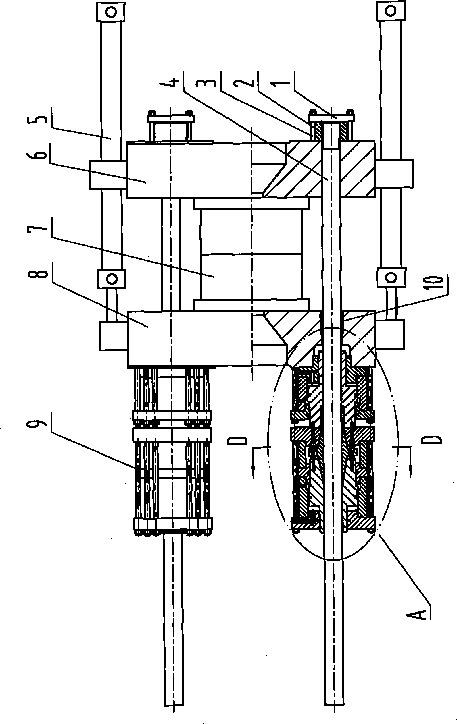
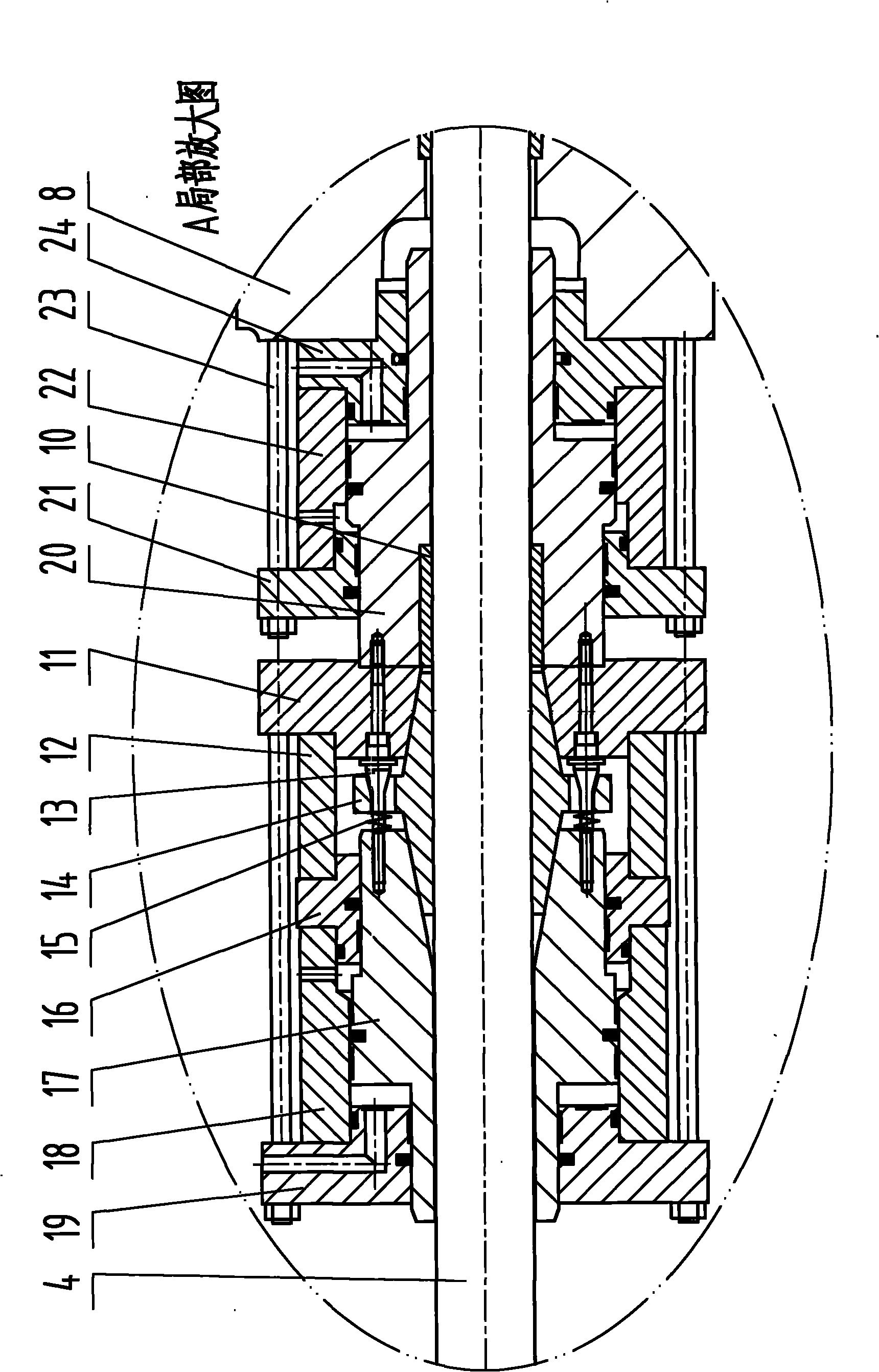
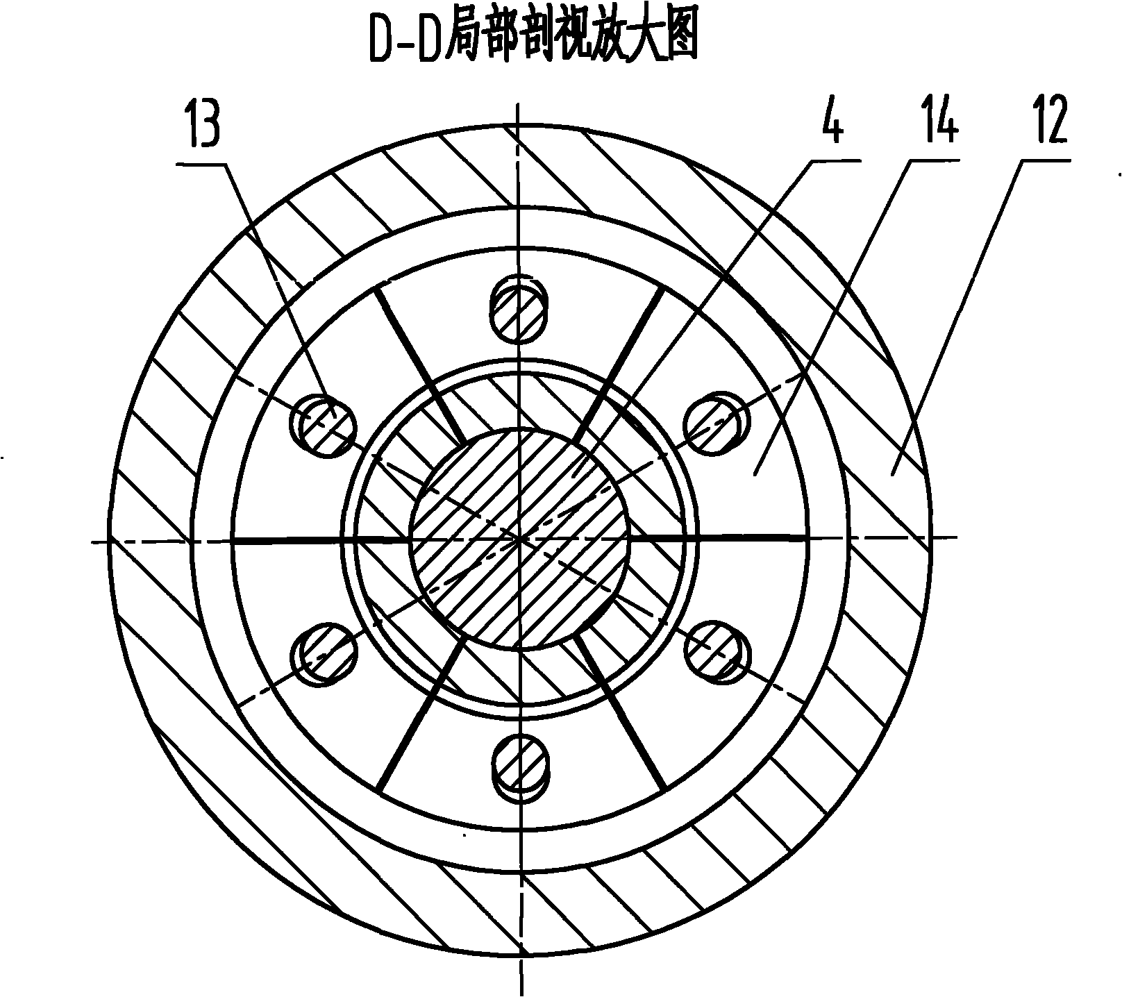
[0017] Such as figure 1 , figure 2 , image 3 , Figure 4 , Figure 5 , Figure 6 As shown in the figure, a hydraulic mold clamping mechanism of the expansion-tightening type, which includes a tie rod clamp (1), a draw rod nut (2), a draw rod clamp screw (3), a draw rod (4), a mold transfer cylinder (5), a fixed template (6), mold (7), movable formwork (8), expansion joint cylinder pull rod (9), guide sleeve (10), expansion support seat (11), support body (12), pull screw (13) , expansion and tight oblique block (14), compression spring (15), expansion and tight engagement oil cylinder back cover (16), expansion and tight engagement oil cylinder piston rod (17), expansion and tight engagement oil cylinder body (18), expansion and tight engagement oil cylinder front cover (19), high pressure mold clamping cylinder piston rod (20), high pressure mold clamping cylinder rear cover (21), high pressure mold clamping cylinder body (22), high pressure mold clamping cylinder pull...


PUM


Abstract

The invention relates to an expansion clasping hydraulic mould locking mechanism, which comprises a pull rod pressing plate, a pull rod nut, a pull rod pressing plate screw, a pull rod, a mould moving oil cylinder, a fixed template, a mould, a movable template, an expansion clasping oil cylinder pull rod, a guide sleeve, an expansion supporting seat, a supporting body, a pull screw, an expansion oblique block, a compression spring, an expansion clasping oil cylinder rear cover, an expansion clasping oil cylinder piston rod, an expansion clasping oil cylinder body, an expansion clasping oil cylinder front cover, a high-pressure mould locking oil cylinder piston rod, a high-pressure mould locking oil cylinder rear cover, a high-pressure mould locking oil cylinder body, a high-pressure mould locking oil cylinder pull rod and a high-pressure mould locking oil cylinder front cover. The mechanism ensures that huge clasping force is generated between an inner ring of the expansion oblique block and the pull rod through hydraulic thrust according to an oblique surface principle, an expansion clasping oil cylinder generates high pressure to clasp the pull rod, and a high-pressure mould locking oil cylinder generates high pressure to generate mould locking force, so that the mould is locked quickly, accurately and reliably.

Description

Technical field [0001] The invention relates to a hydraulic mold clamping mechanism of an expansion and engagement type. Background technique [0002] The traditional hydraulic mold clamping mechanism can be divided into direct pressure mold clamping mechanism and brake type mold clamping mechanism; the disadvantage of direct pressure mold clamping mechanism: because the rapid mold movement and high pressure mold clamping are realized by four clamping cylinders, When the mold is moved quickly, the speed of the mold is slowed down due to the exchange of a large amount of hydraulic oil, and the mold expansion force caused by the injection makes the long-stroke oil of the clamping cylinder compressed to cause the mold to let go; the lock-type mold clamping mechanism Disadvantages: The precise brake action is complex and time-consuming. Repeatedly opening the brake will cause mechanical wear on the teeth on the brake and the tie rod, and the teeth on the tie rod will reduce the ...

Claims


Application Information

Patent Timeline
Patent Type & Authority Applications(China)
IPC IPC(8): B29C33/24B29C45/67B22D17/26
Inventor 叶廷璧
Owner 叶廷璧
Why Eureka
Eureka Blog
Learn More