Eureka AIR delivers breakthrough ideas for toughest innovation challenges, trusted by R&D personnel around the world.

Machining center clamping head assembly

A machining center and collet technology, applied in metal processing machinery parts, metal processing equipment, clamping and other directions, can solve the problems of increased scrap rate, deformation, affecting production efficiency, etc., to improve production efficiency, easy to use, simple structure Effect

Pending Publication Date: 2018-08-10
无锡德申精密机械制造有限公司
View PDF0 Cites 0 Cited by
  • Summary
  • Abstract
  • Description
  • Claims
  • Application Information

AI Technical Summary

Problems solved by technology

[0002] At present, the processing of thin-walled parts on the machining center is clamped by a three-jaw chuck, but this clamping method is only fixed at three points, and it is very easy to deform during processing for thin-walled parts, making them scrapped. The efficiency is greatly improved, which seriously affects the production efficiency

Method used


Image

  • Machining center clamping head assembly

Examples


Embodiment Construction

[0015] Specific embodiments of the present invention will be described below.

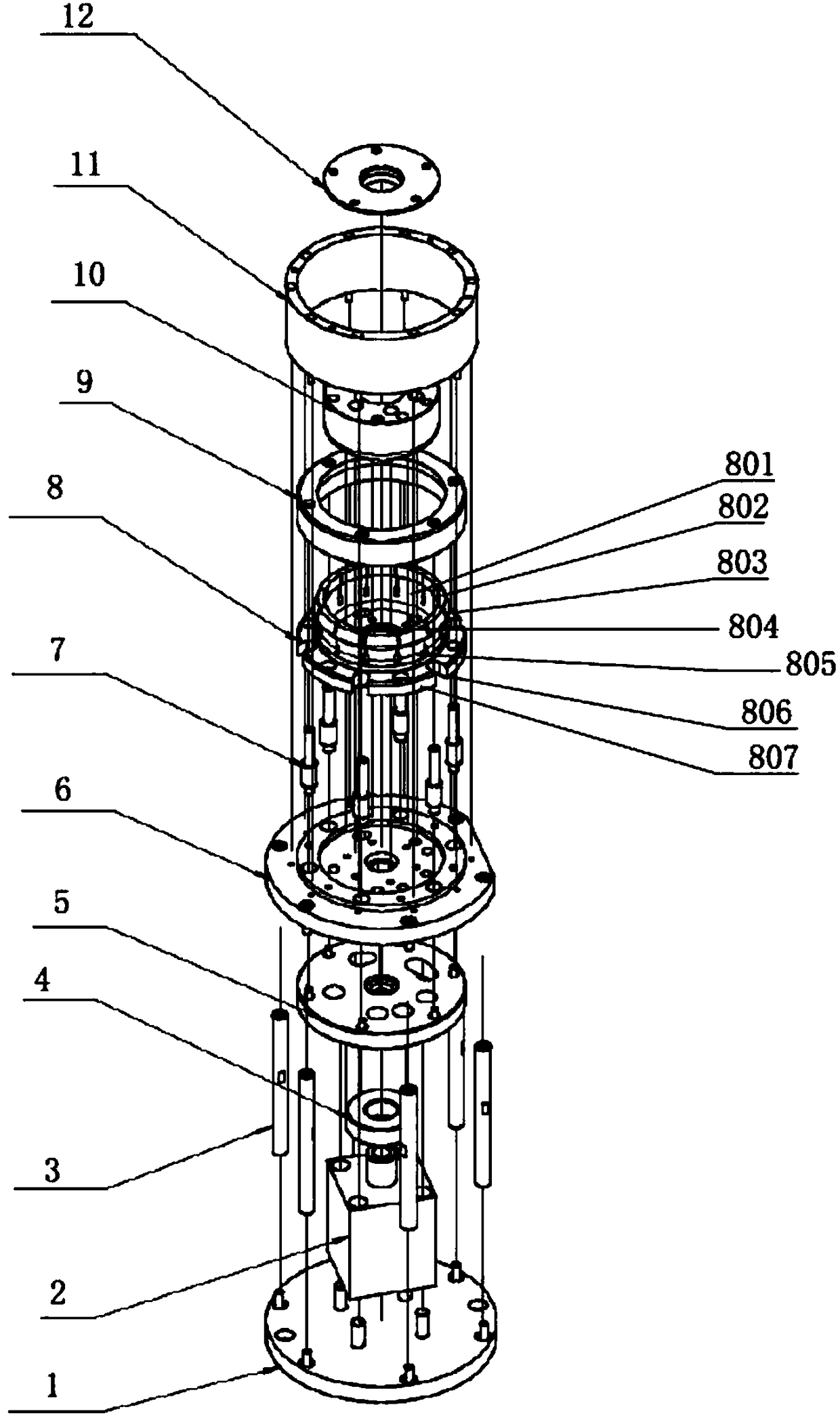
[0016] Such as figure 1 As shown, a chuck assembly of a machining center includes a fixture lower plate 1, on which a plurality of fixture pillars 3 are connected to the fixture upper plate 6; The output end is connected to the connection plate 5 through the limit block 4, the connection plate 5 is pinned to the lower surface of the fixture upper plate 6, and a plurality of guide assemblies 7 are arranged on the upper surface of the fixture upper plate 6, and the guide assemblies are composed of guide posts and matching It consists of a guide sleeve on the outer periphery of the guide post. Each guide assembly 7 is connected with the indenter 9, and the elastic collet 8 used to cooperate with the indenter 9 is also pinned on the surface of the upper plate 6 of the fixture, and the positioning block for matching the part 12 is installed inside the elastic collet 8 10. The supporting sleeve 11 is ...


PUM


Abstract

The invention relates to a machining center clamping head assembly. The machining center clamping head assembly comprises a clamp lower plate, and the clamp lower plate is connected with a clamp upperplate through a plurality of clamp support columns. The surface of the clamp upper plate is further in pin joint with an oil cylinder, and the output end of the oil cylinder is connected with a connecting plate through a limiting block. The connecting plate is in pin joint with the lower surface of the clamp upper plate. The upper surface of the clamp upper plate is further provided with a plurality of guiding assemblies. Each guiding assembly is connected with a pressing head. The surface of the clamp upper plate is further in pin joint with an elastic clamping head used for being matched with the pressing head. A positioning block used for being matched with a component is arranged in the elastic clamping head. The machining center clamping head assembly is simple in structure and convenient to use. By utilization of the machining center clamping head assembly, rapid tight holding of the thin-wall type component on a machining center can be achieved, the machining center clamping head assembly cannot damage the surface of the thin-wall type component, deformation of the thin-wall type component is effectively avoided as well, the beneficial effect of stable clamping is achieved,and the production efficiency is greatly improved.

Description

technical field [0001] The invention relates to the field of mechanical equipment, in particular to a chuck assembly of a machining center. Background technique [0002] At present, the processing of thin-walled parts on the machining center is clamped by a three-jaw chuck, but this clamping method is only fixed at three points, and it is very easy to deform during processing for thin-walled parts, making them scrapped. The efficiency has been greatly improved, which has seriously affected the production efficiency. Contents of the invention [0003] In view of the above-mentioned existing problems, the applicant has made researches and improvements, and provides a chuck assembly of a machining center, which can not only effectively realize the tightening of thin-walled parts, but also greatly reduce the scrap rate. [0004] The technical scheme adopted in the present invention is as follows: [0005] A chuck assembly of a machining center, comprising a fixture lower pla...

Claims


Application Information

Patent Timeline
Patent Type & Authority Applications(China)
IPC IPC(8): B23Q3/00
CPCB23Q3/00B23Q2703/04B23Q2703/10
Inventor 董健
Owner 无锡德申精密机械制造有限公司
Why Eureka
Eureka Blog
Learn More