Eureka AIR delivers breakthrough ideas for toughest innovation challenges, trusted by R&D personnel around the world.

Flow guiding structure in inner part of volute-free fan

A fan and inner panel technology, applied to mechanical equipment, machines/engines, liquid fuel engines, etc., can solve the problems of low efficiency of shellless fans, disordered air flow organization, lack of flow guide devices, etc., to improve fan efficiency and reduce operation Energy consumption and airflow noise reduction effects

Active Publication Date: 2013-01-02
SHANDONG GRAD GROUP +1
View PDF0 Cites 0 Cited by
  • Summary
  • Abstract
  • Description
  • Claims
  • Application Information

AI Technical Summary

Problems solved by technology

[0002] Usually, a caseless fan is composed of a check valve, a collector, a centrifugal impeller, a motor, an outer cover, and sound-absorbing cotton. Since there is no volute, in the working state, the airflow lacks a guide device after the outlet of the impeller, and the outlet cross-section Sudden expansion, large pressure loss, and disordered airflow in the outer cover, a large number of vortices are likely to be generated at the inner corners of the outer cover, the noise is large, and energy loss is caused, so the efficiency of the shellless fan is generally low

Method used


Image

  • Flow guiding structure in inner part of volute-free fan
  • Flow guiding structure in inner part of volute-free fan
  • Flow guiding structure in inner part of volute-free fan

Examples


Embodiment Construction

[0024] The present invention is described in further detail below in conjunction with accompanying drawing:

[0025] The technical solution of the present invention will be further described below in conjunction with the accompanying drawings.

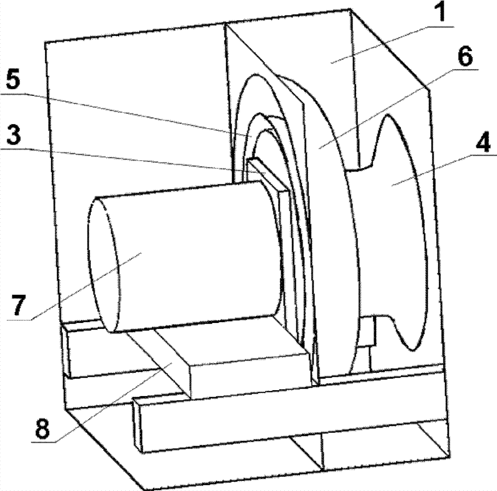
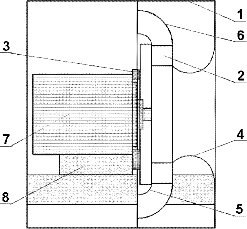
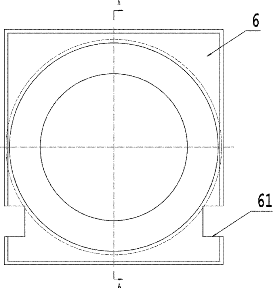
[0026] The schematic diagram of the shellless fan with flow guiding structure of the present invention is as follows: figure 1 As shown, it includes an outer square cover 1, an impeller 2, a fixed plate 3, a current collector 4, an inner guide plate 5, an outer guide plate 6, a motor 7, and an electrode support 8. The motor 7 is fixed on the motor support 8; one side of the fixed plate 3 is fixedly connected with the flow guide inner plate 5, and the other side is fixedly connected with the motor 7 and the electrode support 8, and the flow guide inner plate 5 is fixed on the motor 7 and the electrode support 8; The guide outer plate 6 is fixedly connected with the inner wall of the outer square cover 1 .

[0027] The schematic diagra...


PUM


Abstract

The invention discloses a flow guiding structure in the inner part of a volute-free fan. The structure comprises an outer square shade, an impellor, a fixed board, a flow collector, a flow guiding inner plate an a flow guiding outer plate; the outlet of the impellor at the inner part of the volute-free fan is provided with an arc flow guiding inner plate and a flow guiding outer plate; and the flow guiding inner plate and the flow guiding outer plate form an arc flow guiding air duct the outlet cross section of which expands continuously. According to the invention, on one hand, the flow field at the inner part of the volute-free fan can be improved effectively, the radial air flow behind the impellor outlet is guided to the axial direction, and the energy loss and noise brought about by vortex is reduced; and on the other hand, the effective conversion of motive pressure and static pressure is realized in the diverging flow guiding air duct behind the impellor outlet, the total pressure and static pressure of the fan outlet are improved, and the fan efficiency can be improved effectively.

Description

Technical field: [0001] The invention relates to a shellless centrifugal fan, in particular to a shellless centrifugal fan with an arc guide structure, which is suitable for air supply units of air conditioners and belongs to the technical field of fluid engineering. Background technique: [0002] Usually, a caseless fan is composed of a check valve, a collector, a centrifugal impeller, a motor, an outer cover, and sound-absorbing cotton. Since there is no volute, in the working state, the airflow lacks a guide device after the outlet of the impeller, and the outlet cross-section Sudden expansion, large pressure loss, and disordered airflow in the outer square cover, a large number of vortices are likely to be generated at the inner corners of the outer square cover, the noise is large, and energy loss is caused, so the efficiency of the shellless fan is generally low. Invention content: [0003] The present invention aims to solve the above-mentioned problems, and provide...

Claims


Application Information

Patent Timeline
Patent Type & Authority Patents(China)
IPC IPC(8): F04D29/44
Inventor 刘艳华管印贵苏厚泉欧阳金城廖明仕
Owner SHANDONG GRAD GROUP
Why Eureka
Eureka Blog
Learn More