Hydraulic control loop of high/low-temperature test bed for automatic transmission valve

A high and low temperature test, automatic transmission technology, applied in the testing of machine/structural components, instruments, and mechanical components, etc., can solve the problem that the oil temperature of the valve body has a great influence, only the engine speed is not taken into account, etc.

Active Publication Date: 2011-08-31
CHONGQING TSINGSHAN IND
View PDF8 Cites 23 Cited by
  • Summary
  • Abstract
  • Description
  • Claims
  • Application Information

AI Technical Summary

Problems solved by technology

[0003]The automatic transmission valve body has a wide working range, and the performance of the valve body is greatly affected by the oil temperature. Conventional hydraulic systems often cannot meet the requirements of a wide range of temperature changes. The performance test needs, so the existing valve body performance test is often carried out at normal temperature or not too high temperature
Authorized invention patent ZL200410020321.4 "automobile automatic transmission control valve body test bench" and utility model patent ZL200420029540.4 "automobile automatic transmission control valve body test bench" introduces an automobile automatic transmission control valve body test bench , the patent literature shows that the system uses a double gear pump, and one pump generates working pressure for the worktable moving hydraulic cylinder and the compression die head hydraulic cylinder during the assembly and disassembly of the test valve body, and generates the main force of the valve body test through the pressure reducing valve. oil pressure, but the pressure reducing valve of this oil circuit can only realize the pressure reducing control, and cannot realize the adjustment of the test flow rate of the test valve body; another pump in the system generates speed regulating oil pressure through the proportional pressure regulating valve, but the general full In the hydraulic control valve body of the electronically controlled automatic transmission, the shift strategy is generally controlled by two parameters based on the accelerator and the vehicle speed. Both the accelerator signal and the vehicle speed signal are collected by the transmission controller TCU through the sensor, and the TCU calculates and judges according to the selected The control strategy for the corresponding shift control, the throttle signal of the patent is applied to the control valve through the throttle drive motor to generate the throttle oil pressure, the vehicle speed signal generates the corresponding speed regulation oil pressure through the aforementioned proportional control valve, the vehicle speed and the throttle The signal is not a sensor electronic control system, but converted into throttle valve oil pressure and speed regulating oil pressure and directly applied to the shift valve, so it can be judged that the system is a fully hydraulically controlled automatic transmission system, because the oil pressure is directly applied to the shift valve. On the control valve, so the shift control law can only be realized by the full mechanical hydraulic method; by reading the independent rights and the dependent rights and Figure 4, it is also found that the temperature control method of the system is not complete, and the system only controls the heating by controlling the heater , combined with the patent specification, the test oil temperature is controlled at 55±5oC, and the performance of the hydraulic system is very sensitive to the oil temperature parameters. -35 oC, so it is required to accurately control the test temperature of the valve body test bench in a wider temperature range, and to improve the design of the hydraulic system accordingly
[0004] Authorized utility model patent ZL 200820190245.5 "Automatic Transmission Control Valve Body Test Bench" introduces an automobile automatic transmission control valve body test bench, patent documents It shows that the test bench uses the first variable frequency motor to simulate the engine speed and drive the oil pump, uses the second variable frequency motor to simulate the vehicle speed, and converts the signal of the speed sensor into a square wave signal to control the two shift solenoid valves. It can be seen that the patent does not involve valves at all. The hydraulic system of the body test system does not involve the control of oil temperature; in addition, the signals of two motor speed sensors are used to drive the shift solenoid valve, only the engine speed is simulated, and the engine throttle signal is not considered. The control of the clutch solenoid valve and the redundant two The shift control of a solenoid valve, because the shift control of other electronically controlled hydraulic AMT, DCT, AT and other automatic transmissions except CVT has two extra valves. Solenoid valve control of torque converter lock-up clutch

Method used


Image

  • Hydraulic control loop of high/low-temperature test bed for automatic transmission valve
  • Hydraulic control loop of high/low-temperature test bed for automatic transmission valve
  • Hydraulic control loop of high/low-temperature test bed for automatic transmission valve

Examples


Embodiment Construction

[0024] Below in conjunction with accompanying drawing, structure and specific working method of the present invention are described in detail:

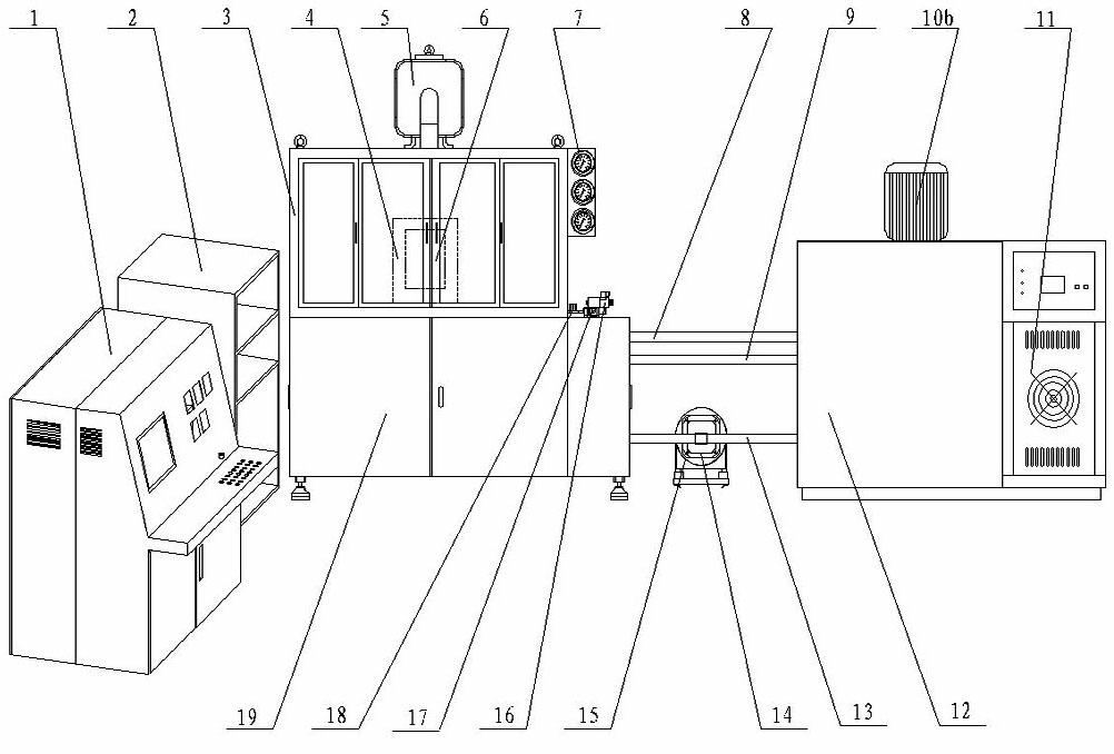
[0025] see figure 1 The automatic transmission valve body high and low temperature hydraulic test bench is mainly composed of control cabinet 1, power box 2, test chamber 3, test valve body connecting plate 4, oil mist collector 5, test valve body 6, pressure gauge 7, low temperature tray oil return pipe 8 , low temperature oil return pipe 9, low temperature system oil tank oil agitator 10, refrigeration unit 11, low temperature system oil tank 12, low temperature oil suction pipe 13, low temperature system oil pump 14, low temperature system servo motor 15, proportional overflow valve 16, system safety valve 17. The main speed regulating valve 18 of the oil inlet circuit, the high-temperature hydraulic pump station 19, and the workbench 100 are composed. Among them, the control cabinet 1 mainly implements the pressure of each ...


PUM


Abstract

The invention discloses a hydraulic control loop of a high / low-temperature test bed for an automatic transmission valve. The system comprises four parts, namely a high-temperature hydraulic oil way, a low-temperature hydraulic oil way, a high / low temperature common oil way, and a measured hydraulic system. In the system, a high / low-temperature hydraulic oil way is divided into two independent systems; the output flow of an oil pump can be adjusted by adjusting the speed of a servo motor; the output pressure of the oil pump can be adjusted by adjusting a proportional valve; and the input flow of a test valve can be stably controlled within a widened range by adjusting speed control valves on a main oil way and a bypass oil way. The high and low-temperature hydraulic oil ways are separated, thereby reducing the demand on the chosen models of parts such as oil pumps, solenoid valves, and the like, and lowering the system cost. In the manner of differentially adjusting the flow by using the speed control valves, the test requirement of controlling a valve in a stable small-flow test condition is simply and reliably realized.

Description

technical field [0001] The invention relates to a test bench for a valve body of an automatic transmission, and in particular to a hydraulic control circuit of a high and low temperature test bench for a valve body of an automatic transmission. Background technique [0002] As the core key component of the automatic transmission, the test valve body plays a vital role in the realization of vehicle functions and the improvement of performance. It not only affects the driving performance and driving comfort of the vehicle, but also affects the efficiency and reliability of the vehicle. Both performance and service life have a major impact. Therefore, it is very important to systematically test the function and performance of the test valve body. The test results are not only the basis for improving the design of the valve body and solenoid valve, but also an important basis for the development of automatic transmission control software. [0003] The working range of the autom...

Claims


Application Information

Patent Timeline
Patent Type & Authority Applications(China)
IPC IPC(8): G01M13/00F15B11/02
Inventor 文红举斯红路侯亚斌银联作孙峰
Owner CHONGQING TSINGSHAN IND
Why Eureka
Try Eureka