Cardiac ablation using microbubbles

a technology of microbubbles and ablation chambers, which is applied in the field of medical procedures and devices for cardiac ablation, can solve problems such as potentially life-threatening conditions, and achieve the effects of reducing the dilution of microbubbles, and increasing the rate of ultrasonic absorption in myocardial tissues

Inactive Publication Date: 2006-05-11
KONINKLIJKE PHILIPS ELECTRONICS NV +1
View PDF24 Cites 30 Cited by
  • Summary
  • Abstract
  • Description
  • Claims
  • Application Information

AI Technical Summary

Benefits of technology

[0013] Ultrasound attenuation of the myocardium is selectively increased with respect to the adjacent venous tissue and with respect to other adjacent structures by introducing microbubbles into the circulatory system so that the microbubbles enter the coronary arteries and pass into the myocardial tissue. The myocardium is highly perfused tissue, receiving its blood supply from the coronary arteries. An injection of microbubbles in the left ventricle (“LV”) results in the movement of microbubbles into the coronary arteries through the aorta, and subsequently perfusion of the myocardium with the microbubbles. An injection of these bubbles into the left atrium (“LA”) will also result in the movement of the microbubbles through the mitral valve into the LV, out of the LV via the aortic root, and into the coronary arteries. An injection into the aorta, for example, at the openings of the coronary arteries, or directly into a particular coronary artery, will provide even more immediate passage of the microbubbles into the myocardial tissue to be ablated, and will minimize dilution of the microbubbles.
[0014] Venous tissue is mostly connective, and not directly or highly vascularized. Therefore, introduction of microbubbles into the blood passing to the heart via the coronary arteries increases the rate of ultrasonic absorption in myocardial tissues to a far greater degree than in venous tissue. As discussed above, certain techniques which have been proposed for treatment of AF direct ultrasonic energy into the wall of the pulmonary vein so as to ablate the myocardial muscular sheathes that extend up the pulmonary veins from the heart. By selectively increasing the rate of ultrasonic absorption of the myocardial tissue, introduction of microbubbles promotes selective heating of the muscular sheathes, and thus limits damage to the venous tissue. This, in turn, helps to avoid stenosis of the pulmonary veins resulting from the treatment. Stated another way, heating of the venous tissue can cause the vein to rapidly occlude. This is a potentially life threatening condition. The preferred techniques according to the present invention can reduce the risk of such vein stenosis.
[0015] Also, regardless of whether the ultrasonic energy is applied in the heart wall or in the vein wall, the enhanced absorption rate of the cardiac tissue allows faster ablation and reduces the total energy which must be delivered during the procedure, which in turn reduces the risk of collateral damage. Additionally, the enhanced absorptivity of the myocardial tissue reduces transmission of ultrasound through the cardiac wall to surrounding structures such as nerves, and thus further reduces the risk of collateral damage. Moreover, by reducing the total energy which must be delivered, the microbubbles reduce the waste heat dissipated by the ultrasonic applicator. Certain ultrasonic applicators disclosed in the applications mentioned above use a balloon filled with an aqueous liquid surrounding a piezoelectric ultrasonic applicator. The fluid is circulated into and out of the balloon to maintain the balloon at a temperature of the balloon below the level of coagulation of the blood, (60-65° C.). By reducing the amount of energy which must be delivered, the need for such circulation can be reduced or eliminated, greatly simplifying the procedure and reducing the cost of the ablation system and catheter.

Problems solved by technology

This is a potentially life threatening condition.

Method used


Image

  • Cardiac ablation using microbubbles
  • Cardiac ablation using microbubbles
  • Cardiac ablation using microbubbles

Examples


Embodiment Construction

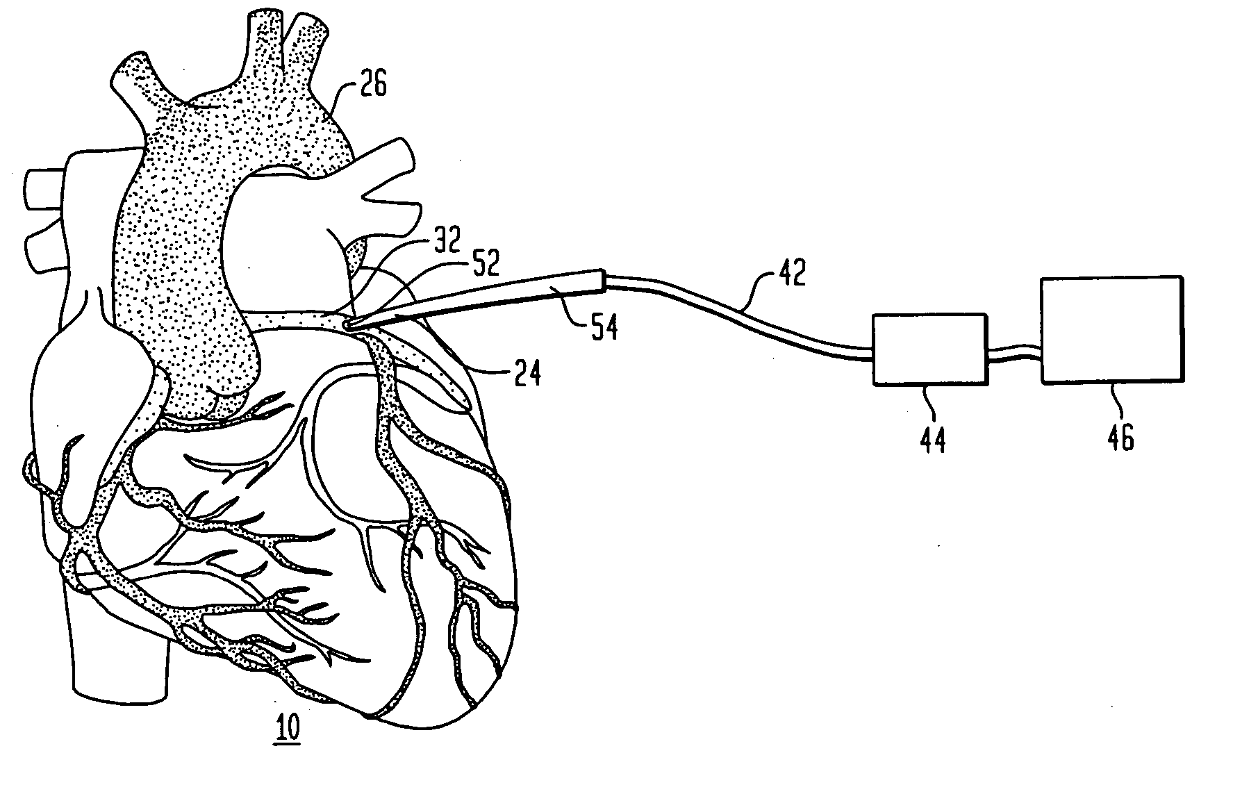
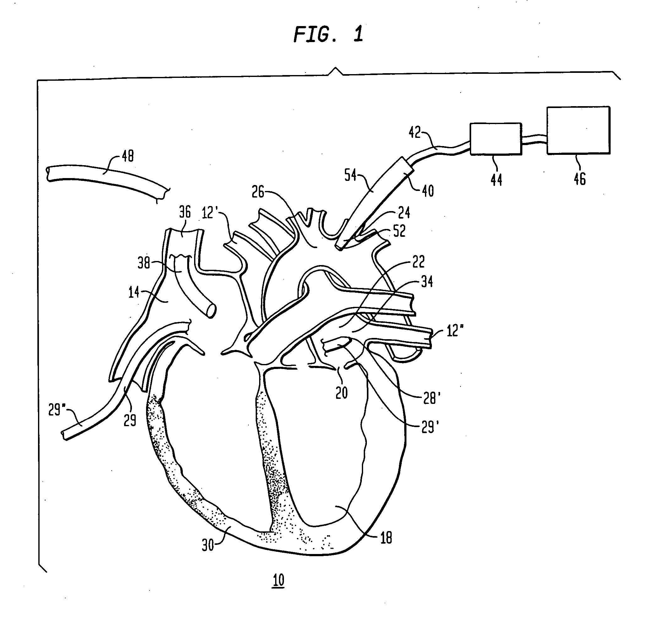
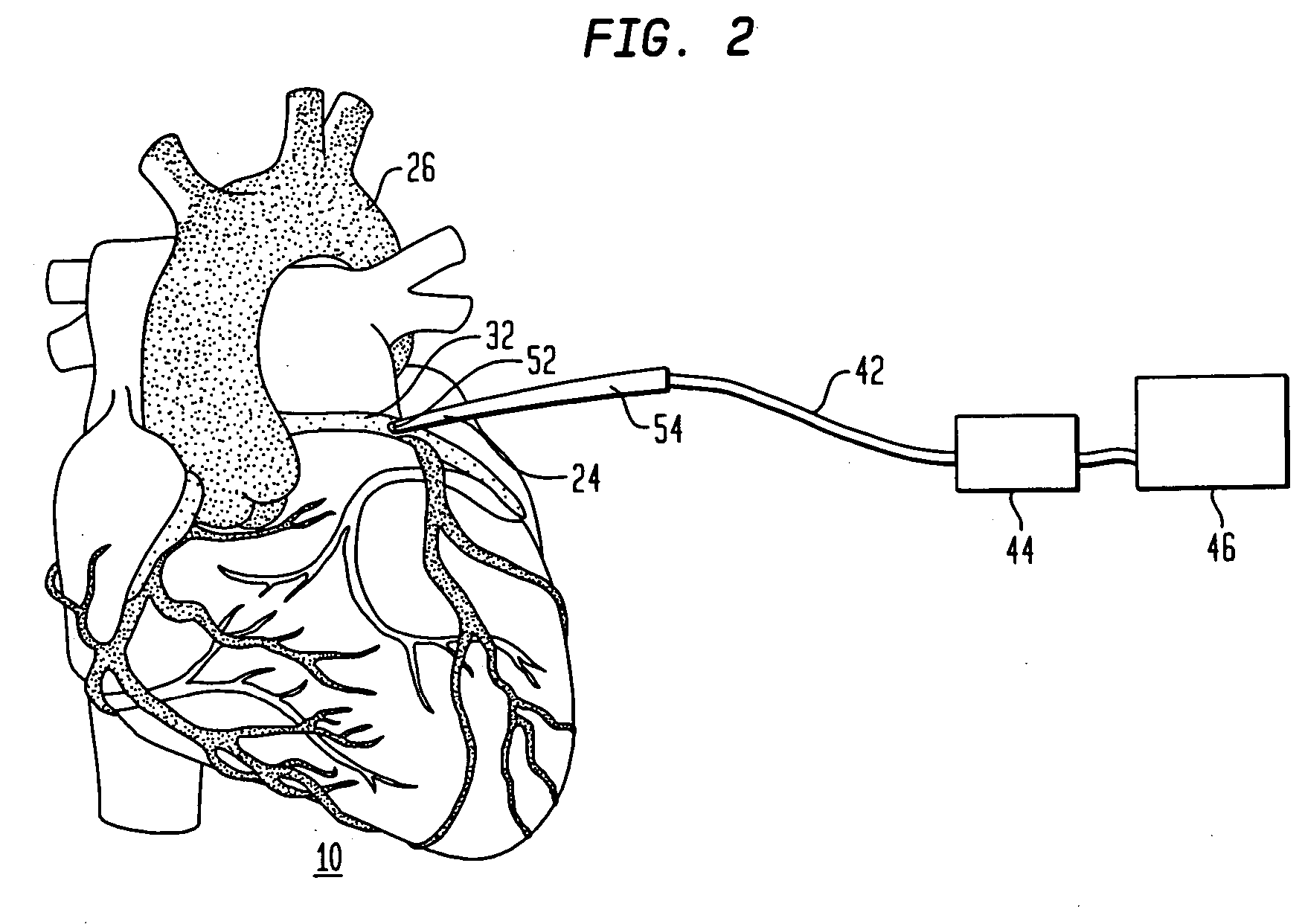
[0022]FIG. 1 shows a method for performing cardiac ablation in accordance with one embodiment of the present invention. The method includes the use of an ultrasonic ablation device 28. Device 28 preferably is a device according to the aforementioned co-pending, commonly assigned U.S. patent application Ser. Nos. 09 / 905,227, 09 / 904,963 and 09 / 904,620, and includes an ultrasonic emitter together with a reflector or lens for focusing the energy emitted from the emitter onto a region of tissue to be ablated. Device 28 desirably is mounted on the distal end 29′ of catheter referred to herein as the device catheter. The proximal end 29″ of the device catheter is connected to a source of excitation energy (not shown) from the ultrasonic device. The apparatus further includes a microbubble catheter 54, and an intracardiac or ultrasound imaging device 48. The distal end of the ultrasonic ablation device 28′ is moved into the heart 10 by a physician. The physician then moves the distal end 29...


PUM


Abstract

In a cardiac ablation procedure, ultrasonic energy is emitted from an ultrasonic ablation device (28) and is focused on myocardial tissue (30) within the wall of the heart or within the wall of a blood vessel connected to the heart (10). Ultrasound attenuation of the cardiac tissue is selectively increased by introducing microbubbles into the circulatory system of the subject so that the microbubbles enter the coronary arteries and pass into the myocardial tissue.

Description

CROSS-REFERENCE TO RELATED APPLICATIONS [0001] The present application claims benefit of U.S. Provisional Patent Application Ser. No. 60 / 394,392, the disclosure of which is incorporated by reference herein.TECHNICAL FIELD [0002] The present invention relates to medical procedures and devices for cardiac ablation and further relates to performing ultrasonic cardiac ablation, or similar medical procedures, with microbubbles. BACKGROND ART [0003] Certain diseases can be treated by ablating tissues within the heart or in the vascular structures connected to the heart. Contraction or “beating” of the heart is controlled by electrical impulses generated at nodes within the heart and transmitted along conductive pathways extending within the wall of the heart. Diseases of the heart known as cardiac arrhythmias involve abnormal generation or conduction of the electrical impulses. One such arrhythmia is atrial fibrillation or “AF”. Certain cardiac arrhythmias can be treated by deliberately d...

Claims


Application Information

Patent Timeline
Patent Type & Authority Applications(United States)
IPC IPC(8): A61B8/12A61B8/00A61B17/00A61B17/22A61N7/02
CPCA61B8/12A61B8/481A61B17/22004A61B17/2202A61B2017/00243A61B2017/22089A61N7/02
Inventor LOPATH, PATRICK DAVID
Owner KONINKLIJKE PHILIPS ELECTRONICS NV
Why Eureka
Try Eureka