Injection mould and manufacturing method thereof

An injection mold and manufacturing method technology, applied in the field of injection mold manufacturing, can solve the problems of defective finished products, time-consuming, manpower and material resources, time-consuming and labor-consuming, etc., so as to improve damage resistance, reduce production costs, and save Effects of materials and costs

Active Publication Date: 2013-01-16
广东邦宝益智玩具有限公司
View PDF7 Cites 0 Cited by
  • Summary
  • Abstract
  • Description
  • Claims
  • Application Information

AI Technical Summary

Problems solved by technology

In the process of injection molding, the sprue and pouring channel have to go through multiple pouring work under high pressure and high temperature environment, and the sprue and pouring channel will be damaged. If the damage is not repaired in time, the subsequent plastic products will appear. Unqualified conditions, for example, will cause a depression in the pouring port of the plastic product, especially when pouring some plastic building blocks and some more precise plastic products, the probability of defective finished products is higher, and the building blocks with cylindrical bumps , the position of the sprue is very prone to failure
Since the sprue and the pouring channel are integrated with the mold, the entire mold must be disassembled to repair the damaged part, which is very difficult and time-consuming and labor-intensive.
If there is a situation that cannot be repaired, the entire insert will be scrapped. It is very wasteful to scrap the entire insert simply because the sprue and the pouring channel cannot be repaired, and it will take time and manpower to remake the same insert and physical resources

Method used


Image

  • Injection mould and manufacturing method thereof
  • Injection mould and manufacturing method thereof

Examples


Embodiment Construction

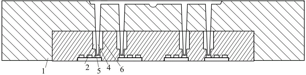
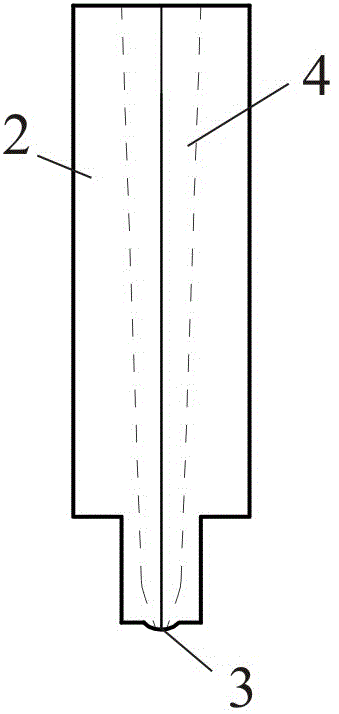
[0018] refer to figure 1 with figure 2 , the purpose of the present invention is an injection mold that can achieve convenient replacement of pouring core parts, increase the service life of the mold and save costs. The invention mainly improves the pouring position at the 5 feeding port of the mold cavity of the injection mold. A detachable pouring core 2 is provided on the mold body. In traditional injection molds, this part is integrated with the mold body, but the innovation of the present invention is to design this part as an independent part independent of the mold body 1, that is, the casting core part 2, the casting core part 2 Of course, there are pouring ports 3 and pouring channels 4. The mold body 1 is provided with a pouring core hole 6 capable of assembling the pouring core 2. The pouring core 2 and the pouring core hole 6 on the mold 1 are connected by a tight fit. Together, that is, the pouring core 2 is fastened on the mold body 1, and the pouring port 3 ...


PUM


Abstract

The invention relates to an injection mould for improving a pouring gate and a manufacturing method of the injection mould, and the mould is provided with a detachable pouring core part. The injection mould comprises the pouring core part which is independent of the injection mould, the pouring core part forms the pouring gate and a pouring channel, the pouring core part and the whole mould can be conveniently separated, when the pouring core part is abraded during the working process and plastic molding is further influenced, the pouring core part can be detached from the mould for replacement, thereby being time-saving and labor-saving during actual applications.

Description

technical field [0001] The invention relates to an injection mold, in particular to an injection mold with an improved sprue, and also relates to a manufacturing method of the injection mold. Background technique [0002] Injection mold is a key part of manufacturing plastic products. There is a cavity on the mold, and the plastic enters the cavity through the pouring channel and the sprue. The sprue and the pouring channel are part of the mould, that is to say, the mold itself, forming the sprue and the pouring channel, the walls of the mold cavity, etc. are all made of the same material. Typically, a set of injection molds produces thousands of plastic parts, sometimes even more. In the process of injection molding, the sprue and pouring channel have to go through multiple pouring work under high pressure and high temperature environment, and the sprue and pouring channel will be damaged. If the damage is not repaired in time, the subsequent plastic products will appear....

Claims


Application Information

Patent Timeline
Patent Type & Authority Patents(China)
IPC IPC(8): B29C45/26B29C33/38
Inventor 吴锭辉
Owner 广东邦宝益智玩具有限公司
Why Eureka
Try Eureka