Treatment system for surgical operation and method of controlling treatment system for surgical operation
A technology of disposal system and control method, which is applied to the parts of surgical instruments, surgery, suction and irrigation systems, etc., and can solve problems such as time-consuming
- Summary
- Abstract
- Description
- Claims
- Application Information
AI Technical Summary
Problems solved by technology
Method used
Image

Examples
no. 1 Embodiment approach
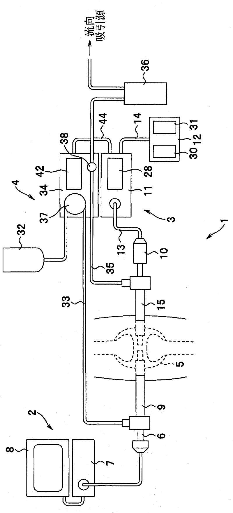
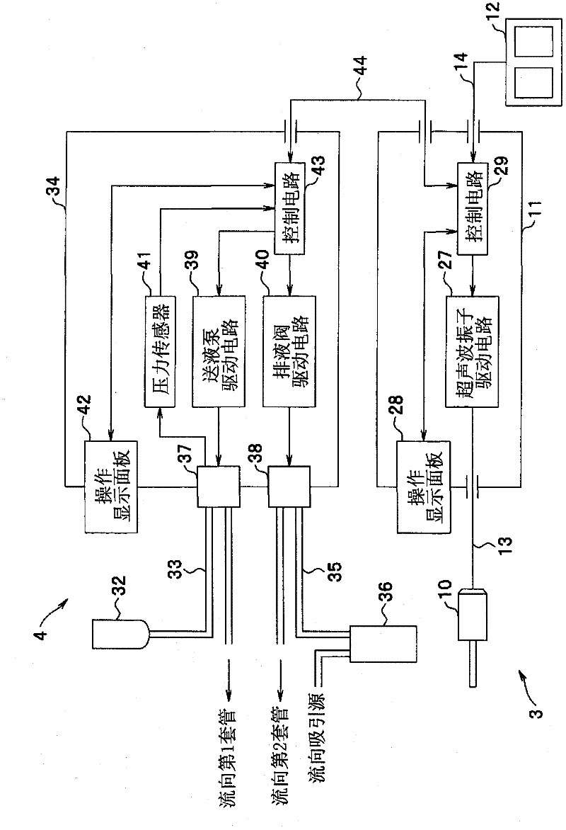
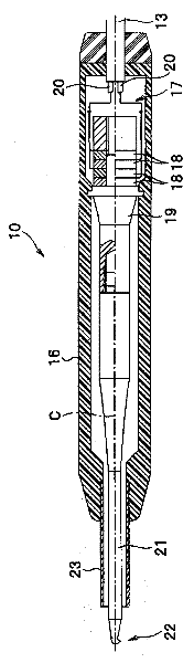
[0037] Figure 1 to Figure 8 It is a diagram for explaining the surgical treatment system according to the first embodiment of the present invention. figure 1 It is a diagram for explaining the overall configuration of the surgical treatment system according to the first embodiment of the present invention. figure 2 It is a block diagram showing the configurations of the surgical treatment device and the perfusion device according to the first embodiment. image 3 It is a cross-sectional view of the handpiece of the first embodiment. Figure 4 It is a perspective view of the treatment part of the hand piece of 1st Embodiment. Figure 5 It is a perspective view of another example of the treatment part of a hand piece. Figure 6 It is a perspective view of another example of the treatment part of a hand piece. Figure 7 and Figure 8 It is a time chart showing the operation of the handpiece drive unit and the perfusion unit.
[0038] (structure)
[0039] Such as figure ...
no. 2 Embodiment approach
[0078] Next, a surgical treatment system according to a second embodiment of the present invention will be described.
[0079] Figure 9 It is a block diagram showing the configurations of the surgical treatment device and the perfusion device according to the second embodiment. exist Figure 9 in, right with figure 2 The same constituent elements are assigned the same reference numerals and descriptions thereof are omitted, and only parts different from those of the first embodiment will be described.
[0080] (structure)
[0081] Such as Figure 9 As shown, in the surgical treatment system 1A of this embodiment, a switch 46 such as a foot switch is connected to the control circuit 43 of the perfusion pump unit 34 via a switch connection cable 47 . Furthermore, the surgical treatment system 1A is configured to input an operation signal from the switch 46 to the control circuit 43 .
[0082] This switch 46 is a switch that drives the control circuit 43 to change the flo...
no. 3 Embodiment approach
[0091] Next, a surgical treatment system according to a third embodiment of the present invention will be described.
[0092] Figure 10 to Figure 18 It is a block diagram showing the configurations of the surgical treatment device and the perfusion device according to the third embodiment. Figure 10 It is a figure for demonstrating the whole structure of the surgical treatment system of 3rd Embodiment. Figure 11 It is a block diagram showing the configurations of the surgical treatment device and the perfusion device according to the third embodiment. Figure 12 It is a structural diagram which shows the structure of the handpiece of 3rd Embodiment. Figure 13 From Figure 12 The A-direction view is observed in the direction of the arrow A. Figure 14 is a cross-sectional view of the handpiece. Figure 15 and Figure 16 It is the external view of the handpiece. Figure 17 and Figure 18 is a time chart showing the operation of the handpiece drive unit and the perfus...
PUM
 Abstract
Description
Claims
Application Information
 - R&D Engineer
- R&D Manager
- IP Professional
- Industry Leading Data Capabilities
- Powerful AI technology
- Patent DNA Extraction
Browse by: Latest US Patents, China's latest patents, Technical Efficacy Thesaurus, Application Domain, Technology Topic.
© 2024 PatSnap. All rights reserved.Legal|Privacy policy|Modern Slavery Act Transparency Statement|Sitemap