Sealing between a combustion chamber and a turbine distributor in a turbine engine

A technology of turbine nozzles and turbines, which is applied to the sealing of engines, gas turbine devices, mechanical equipment, etc., can solve problems such as increasing the risk of cracks, and achieve the effect of good sealing

Active Publication Date: 2011-09-07
SN DETUDE & DE CONSTR DE MOTEURS DAVIATION S N E C M A
View PDF9 Cites 19 Cited by
  • Summary
  • Abstract
  • Description
  • Claims
  • Application Information

AI Technical Summary

Problems solved by technology

It was also observed that the gasket cover therefore does not provide a good seal between the slits and that hot gases may pass between the slits to the outside of the combustion chamber
The downstream end of the combustion chamber wall and the fastening flanges of said wall are then locally exposed to high temperatures, causing stress and increasing the risk of cracks in said element

Method used


Image

  • Sealing between a combustion chamber and a turbine distributor in a turbine engine
  • Sealing between a combustion chamber and a turbine distributor in a turbine engine
  • Sealing between a combustion chamber and a turbine distributor in a turbine engine

Examples


Embodiment Construction

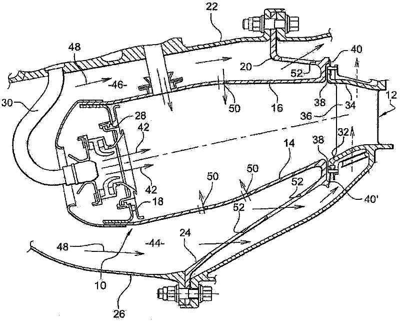
[0031] first reference figure 1 , figure 1 Shown is an annular combustor 10 of a turbomachine, such as an aircraft turboprop or turbojet, arranged downstream of a compressor and diffuser (not shown) and at the inlet nozzle 12 of a high pressure turbine 10 upstream.

[0032] The combustion chamber 10 has an inner wall 14 forming a surface of revolution and an outer wall 16 inside which the inner wall extends and which are connected together at the upstream end by means of an annular chamber end wall 18 . The outer wall 16 of the combustion chamber is connected at the downstream end to an outer annular flange 20 which is fastened at the outer periphery to the outer casing 22 of the combustion chamber, and the inner wall 14 is connected at the downstream end to an inner annular flange 24 which The rim 24 is fastened at the inner periphery to the inner casing 26 of the combustion chamber.

[0033] The annular chamber end wall 18 has an opening 28 for the passage of air from the...


PUM


Abstract

The invention relates to a turbine engine that includes an annular combustion chamber (10), a turbine distributor (12) divided into sectors and arranged at the outlet of the chamber, and a sealing means provided axially between the chamber and the distributor, the sealing means including an axially elastic annular seal (70, 70') comprising an axial bearing means on a downstream end of the chamber and an annular downstream lip divided into sectors, each sector of the downstream lip being aligned with a sector of the distributor and comprising an axial bearing means on an upstream end of the distributor sector.

Description

technical field [0001] The invention relates to a seal between the annular combustion chamber and the turbine nozzle of a turbomachine, such as an aircraft turboprop or turbojet. Background technique [0002] The turbine combustion chamber comprises two coaxial walls forming surfaces of revolution, constituting respectively an inner and an outer wall and delimiting a combustion chamber therebetween, each connected at its downstream end to a casing for fastening to the turbine corresponding annular flange on the [0003] A segmented turbine nozzle is arranged at the exit of the combustion chamber and includes one or more annular platforms (eg two platforms, respectively comprising an inner platform and an outer platform) connected by generally radial vanes. The inner and outer platforms of the nozzle extend generally axially in alignment with the inner and outer walls of the combustion chamber, respectively. The upstream end of the nozzle platform is axially spaced from the...

Claims


Application Information

Patent Timeline
Patent Type & Authority Applications(China)
IPC IPC(8): F01D9/02F01D11/00F02C7/28F16J15/02
CPCF01D11/005F02C7/28Y02T50/675F01D9/023F16J15/0887Y02T50/60
Inventor 克里斯托夫·皮乌瑟尔戈斯丹尼斯·吉恩·莫里斯·桑德里斯
Owner SN DETUDE & DE CONSTR DE MOTEURS DAVIATION S N E C M A
Why Eureka
Try Eureka