Multifunctional car tire inflator pump
A technology for automobile tires and air pumps, applied in the field of automobile tire air pumps, can solve problems such as time-consuming and labor-intensive, and achieve the effects of convenient lighting, neat structure, and small volume
- Summary
- Abstract
- Description
- Claims
- Application Information
AI Technical Summary
Problems solved by technology
Method used
Image
Examples
Embodiment 1
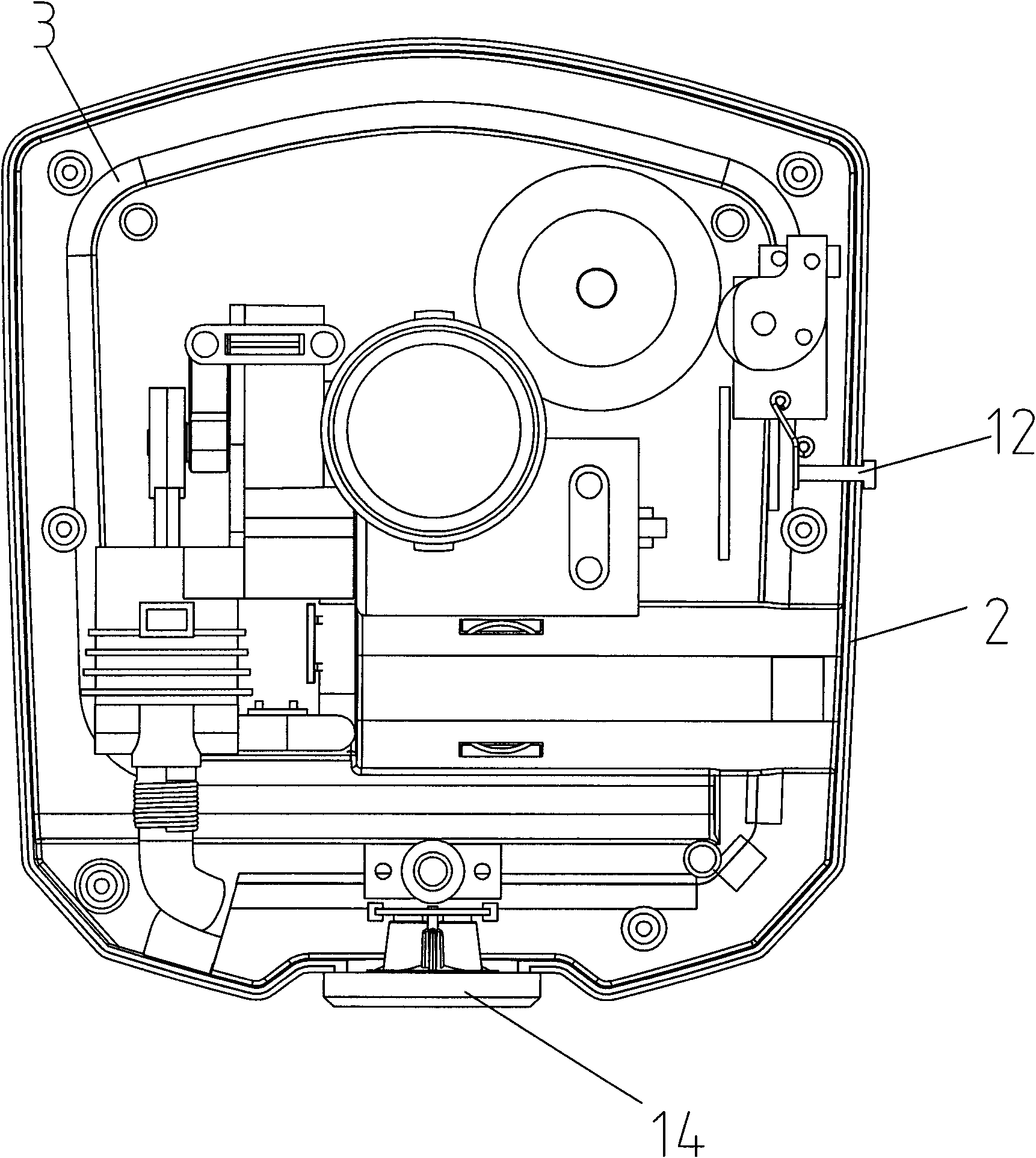
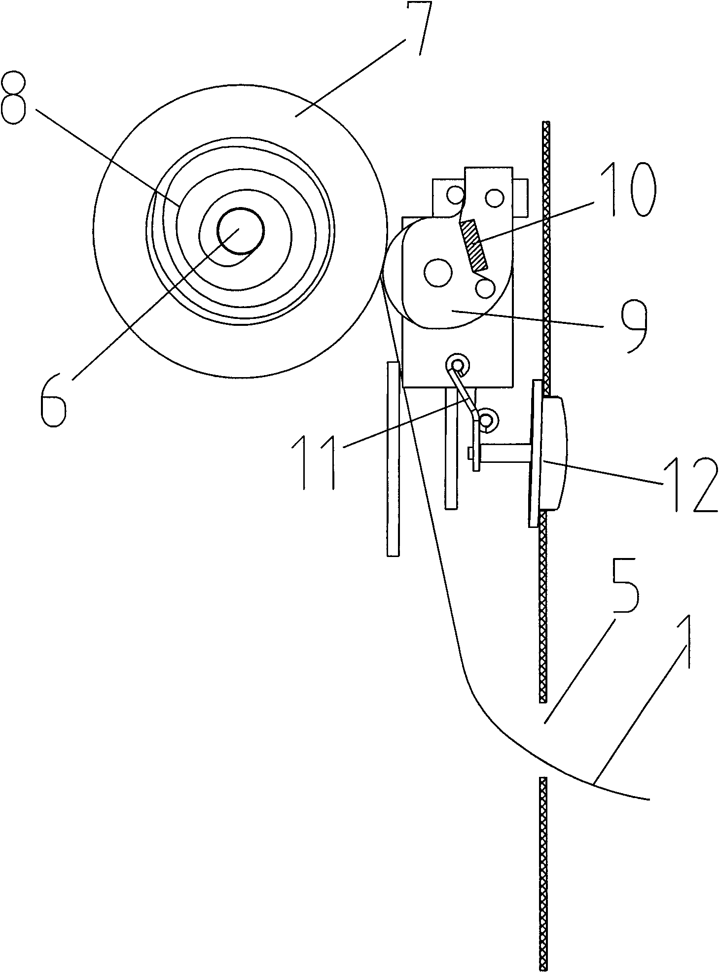
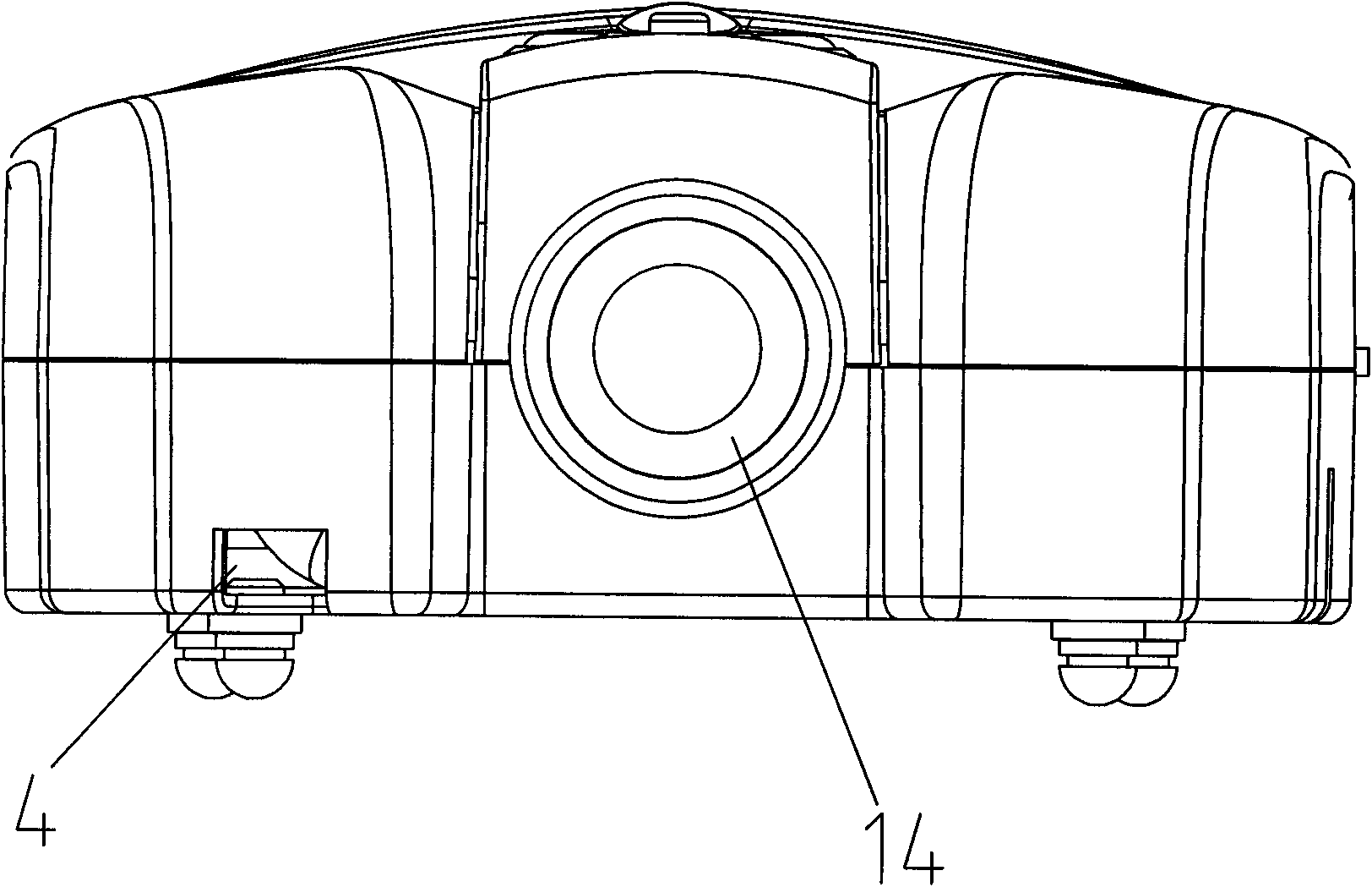
[0018] refer to figure 1 , figure 2 , image 3 , a multifunctional automobile tire air pump, comprising a power cord 1, a casing 2, an air outlet pipe 3 inside the casing, the casing 1 is provided with an outlet pipe outlet 4 and a power cord outlet 5, and the casing A rotating shaft 6 is provided inside the body 1, and a reel 7 is threaded on the revolving shaft, and the power cord 1 is coiled on the reel 7; between the reel 7 and the reel 6 there is A clockwork spring 8, one end of the clockwork spring 8 is connected to the rotating shaft 6, and the other end of the clockwork spring 8 is connected to the coil 7;
[0019] The housing next to the wire reel 7 is hinged with a stop wheel 9, and the edge of the stop wheel 9 is in close contact with the edge of the wire reel 7; it also includes a first spring 10, and one end of the first spring 10 is connected to the On the housing 2, the other end of the first spring 10 is connected to the stop wheel 9 so that the stop wheel ...
Embodiment 2
[0025] refer to Figure 4 , a multi-functional automobile tire air pump, comprising a power cord 1, a housing 2, an air outlet pipe in the housing 2, the housing 2 is provided with an air outlet pipe outlet and a power cord outlet, and the housing 2 is provided with a rotating shaft 6, the rotating shaft 6 is pierced with a reel 7, and the power cord is coiled on the reel 7; between the reel 7 and the rotating shaft 6 there is a A bar spring 8, one end of the clockwork spring 8 is connected to the rotating shaft 6, and the other end of the clockwork spring 8 is connected to the coil 7;
[0026] There is also a stop wheel 9 in the housing next to the wire reel 7, and the edge of the stop wheel 9 is in close contact with the edge of the wire reel 7. Disengaged stop wheel drive mechanism. In this embodiment, the driving mechanism is as follows: a pivot 14 is arranged inside the housing, a torsion spring is threaded on the pivot 14, and a rocker arm 13 is threaded on the pivot o...
PUM
 Abstract
Description
Claims
Application Information
 - R&D
- Intellectual Property
- Life Sciences
- Materials
- Tech Scout
- Unparalleled Data Quality
- Higher Quality Content
- 60% Fewer Hallucinations
Browse by: Latest US Patents, China's latest patents, Technical Efficacy Thesaurus, Application Domain, Technology Topic, Popular Technical Reports.
© 2025 PatSnap. All rights reserved.Legal|Privacy policy|Modern Slavery Act Transparency Statement|Sitemap|About US| Contact US: help@patsnap.com


