
Dolly for overhead and gantry cranes

A crane and trolley technology, which is applied in the direction of load-carrying pulley, traveling mechanism, clockwork mechanism, etc., can solve the problems of increasing the bearing capacity of the main beam of the crane, the weight of the trolley, and the high energy consumption, so as to reduce the weight and cost, and reduce the height of the building. , the effect of reducing construction costs

Active Publication Date: 2011-09-14
宁波市凹凸重工有限公司
View PDF6 Cites 4 Cited by
  • Summary
  • Abstract
  • Description
  • Claims
  • Application Information

AI Technical Summary

Problems solved by technology

[0003] 1. Since the motor, reducer and reel are all installed on the platform, and the platform is composed of end beams and main beams welded to form a frame structure and a flat plate is laid on the upper end of the frame, therefore, the overall height of the trolley is relatively high, thus Make the building height of the factory building that accommodates the gantry crane relatively high, increasing the construction cost of the factory building
[0004] 2. Since the fixed pulley block is installed on the frame and located under the reel, it is very inconvenient to repair the fixed pulley block after removing the reel before proceeding.
[0005] 3. Since the frame includes two end beams and two main beams, the end beams and main beams are welded to form a frame structure, and a flat plate is laid on the upper end of the frame to form a platform, so that the weight of the trolley is relatively heavy, so that in the same tonnage The bearing capacity of the main girder of the crane is increased, which increases the manufacturing cost of the whole crane, and the energy consumption is also high.

Method used


Image

  • Dolly for overhead and gantry cranes
  • Dolly for overhead and gantry cranes
  • Dolly for overhead and gantry cranes

Examples


Embodiment Construction

[0024] The present invention will be further described below in conjunction with the accompanying drawings and specific embodiments.

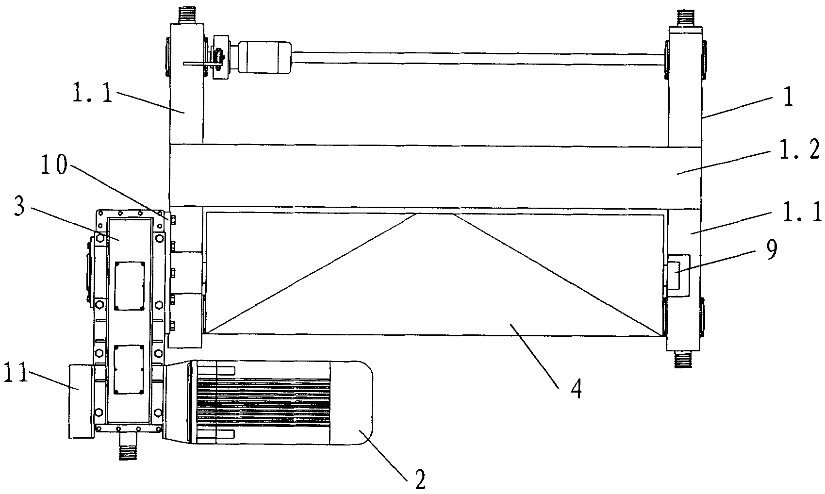
[0025] see image 3 , Figure 4 and Figure 5 As shown, the trolley for the gantry crane of the present invention has a lifting mechanism comprising a vehicle frame 1, a motor 2, a reducer 3, a reel 4, a fixed pulley block 5, a hook 6, a driving wheel set 7 and a driven wheel set 8. The vehicle frame 1 includes an end beam 1.1 and a main beam 1.2, the two end beams 1.1 are two, the main beam 1.2 is one, and the two end beams 1.1 are fixed on the main beam respectively. The two ends of the beam 1.2 form a frame structure, and the ends of the main beam 1.2 are respectively located at the middle positions of the two end beams 1.1. The reel 4 is located in the frame structure and parallel to the main beam 1.2. The reel 4 is rotatably mounted on the two end beams 1.1. In this specific embodiment, the two ends of the reel 4 are axially limited b...


PUM


Abstract

The invention discloses a dolly for overhead and gantry cranes. A hoisting mechanism comprises a car frame (1), a motor (2), a speed reducer (3), a winding drum (4), a fixed pulley group (5) and a lifting hook (6); the car frame (1) comprises two end beams (1.1) and a main beam (1.2); the end beams (1.1) and the main beam (1.2) form a framework structure; the winding drum (4) is positioned in theframework structure; the winding drum (4) is rotationally installed on the two end beams (1.1); the speed reducer (3) is installed on the side wall of one of the end beams (1.1); a low-speed shaft ofthe speed reducer (3) is connected with the end part of the winding drum (4) installed on the end beam (1.1); the motor (2) is installed on the side wall of the speed reducer (3); and an output shaftof the motor (2) is connected with a high-speed shaft of the speed reducer (3). The dolly has low height, is convenient to maintain, and has light weight and low energy consumption.

Description

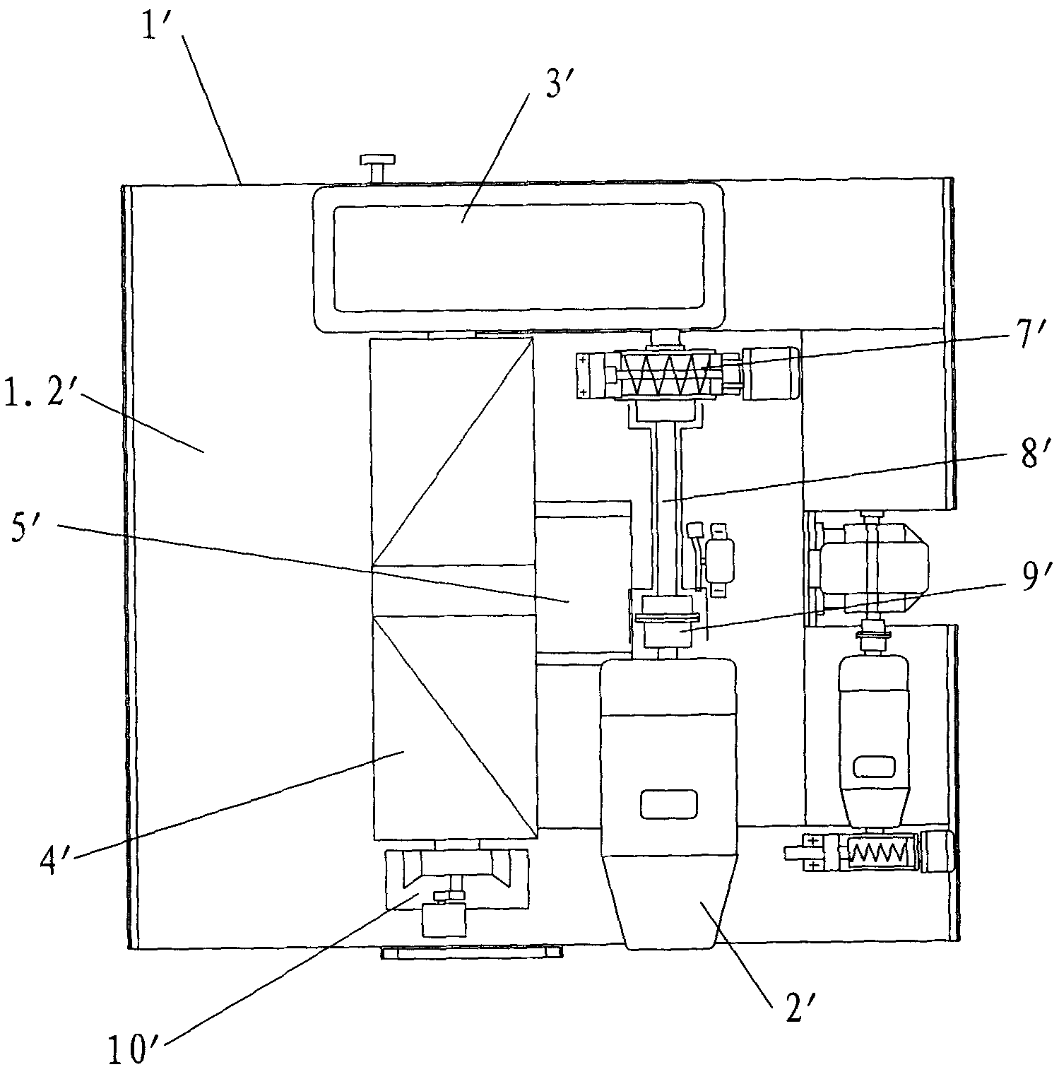
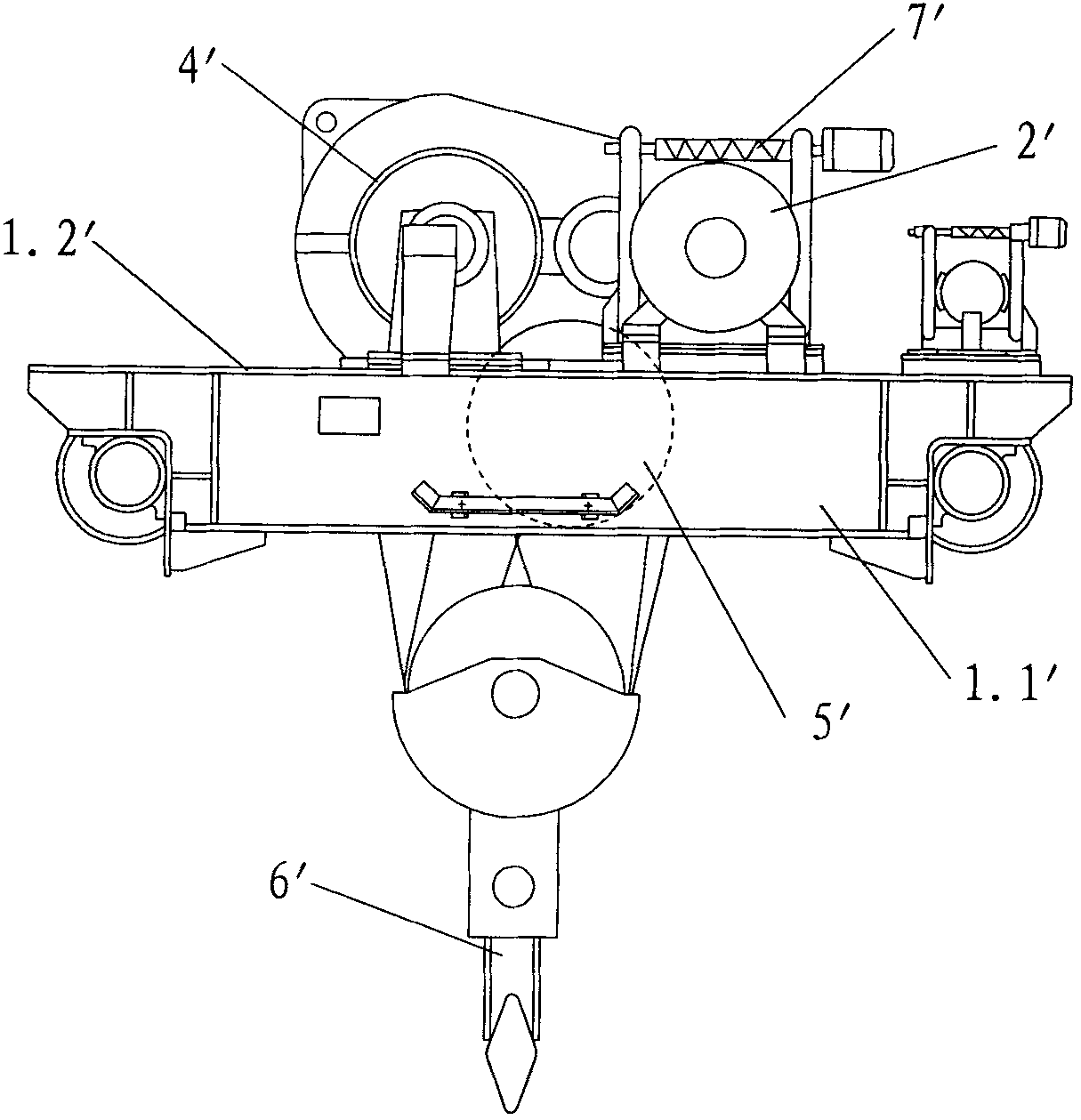
technical field [0001] The invention relates to a trolley for a bridge gantry crane. Background technique [0002] Gantry cranes are widely used in power plants, freight yards, workshops, docks, etc. for loading and unloading of bulk materials. Gantry crane mainly includes steel structure, trolley and electrical control part. see figure 1 and figure 2 As shown, standard trolleys with unified design are generally used in China now, and its lifting mechanism includes frame 1', motor 2', reducer 3', reel 4', fixed pulley block 5' and hook 6'. The frame 1' includes two end beams 1.1' and two main beams (not shown), the end beams 1.1' and the main beams are welded to form a frame structure, and a flat plate is laid on the upper end of the frame to form a platform 1.2' . Described motor 2', speed reducer 3', reel 4' are all installed on the described platform 1.2'. The reel 4' is installed on the platform 1.2', one end of the reel 4' is installed on the support 10' fixed on...

Claims


Application Information

Patent Timeline
Patent Type & Authority Applications(China)
IPC IPC(8): B66C11/00B66C11/16B66C9/10B66D1/12B66D1/30
Inventor 洪余力朱剑君高锋朱广超
Owner 宁波市凹凸重工有限公司
Learn More