
High-speed torsion testing machine

A torsion testing machine, high-speed technology, applied in the direction of measuring devices, instruments, scientific instruments, etc., can solve the problems of difficulty in realization, consume a lot of electric energy, etc., and achieve the effect of saving test energy consumption

Active Publication Date: 2011-09-14
JILIN DAHUA MACHINERY MANUFACTURING CO LTD
View PDF6 Cites 23 Cited by
  • Summary
  • Abstract
  • Description
  • Claims
  • Application Information

AI Technical Summary

Problems solved by technology

This solution is difficult to realize in the design and manufacture of the actual test bench for high-speed and high-torque transmission components. For example, under the working conditions of 5000rpm and 1000Nm, the power of the driving motor needs to be 500KW, and the test process will consume a lot of electric energy.

Method used


Image

  • High-speed torsion testing machine
  • High-speed torsion testing machine
  • High-speed torsion testing machine

Examples


Embodiment Construction

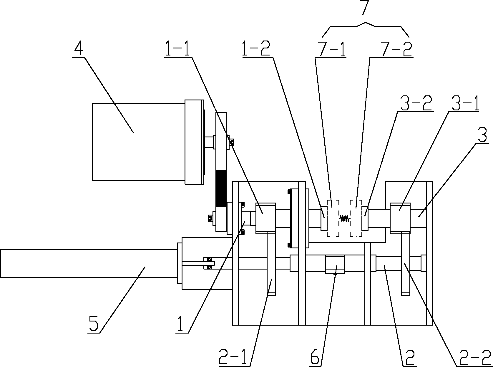
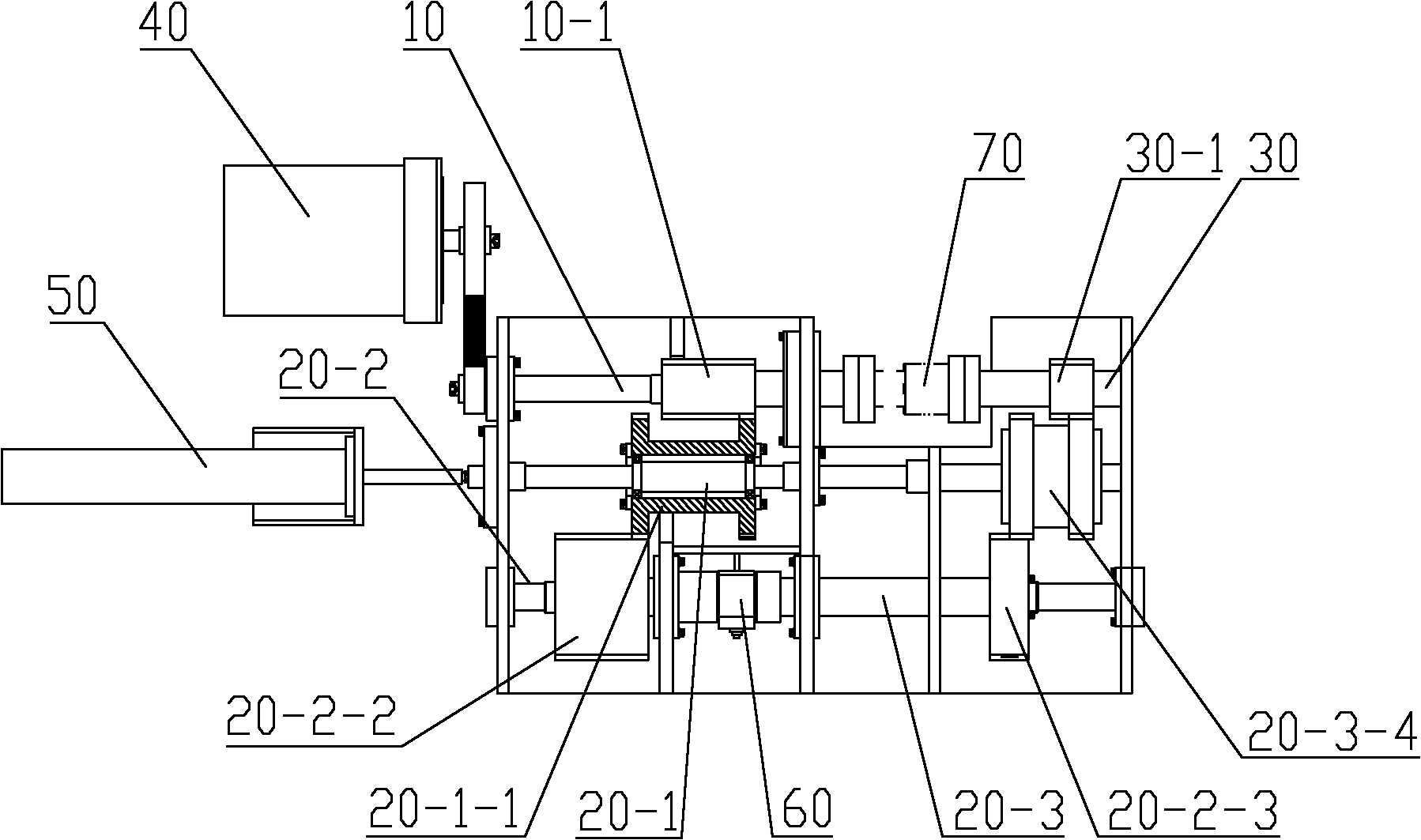
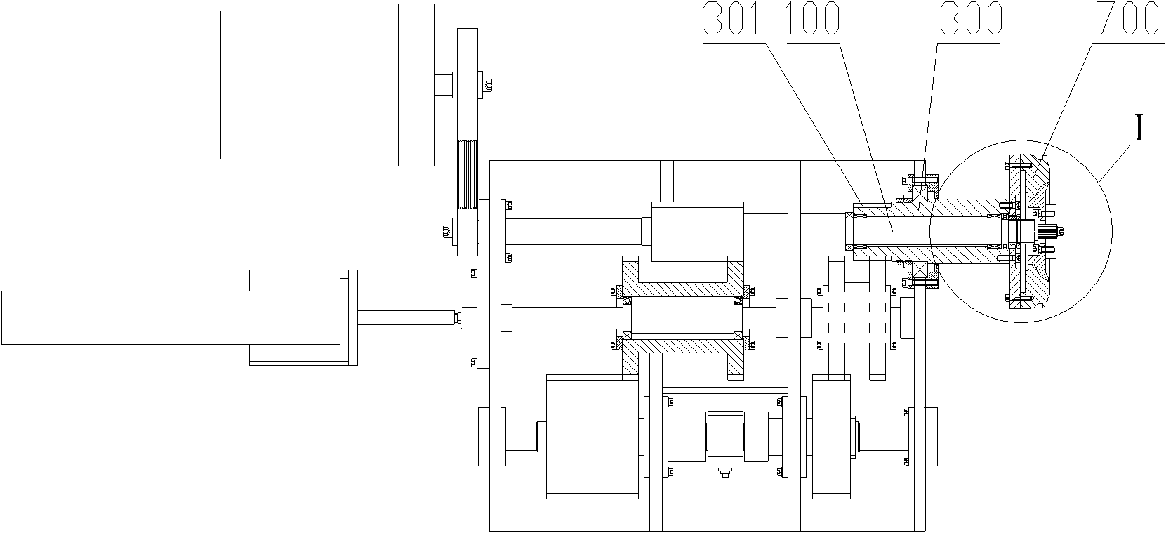
[0028] The core of the present invention is to provide a high-speed torsion testing machine capable of performing high-speed torsion tests on rotating workpieces.

[0029] In order to enable those skilled in the art to better understand the solution of the present invention, the present invention will be further described in detail below in conjunction with the accompanying drawings and specific embodiments.

[0030] The terminology such as "up, down, left, right" in this article indicating orientation is based on the positional relationship of the drawings, and should not be interpreted as an absolute limit to the scope of protection. The terms "first, second" are only for It is convenient for description to distinguish different components with the same name, and does not indicate a sequence or a primary and secondary relationship.

[0031] Please refer to figure 1 , figure 1 It is a structural schematic diagram of the first embodiment of the high-speed torsion testing mac...


PUM


Abstract

The invention discloses a high-speed torsion testing machine which comprises a driving shaft driven by a motor and a driven shaft coaxially arranged with the driving shaft, wherein a driving gear is arranged on the driving shaft, a driven gear is arranged on the driven shaft, the driving gear and the driven gear are in transmission connection through a transmission shaft provided with a transmission gear, the transmission shaft is provided with a servo system for controlling the transmission shaft to axially move, and the driving gear and / or the driven gear are / is a bevel gear. When the driving gear performs axial reciprocating movement, the acting force to the driving shaft and the driven gear is formed, and the rotating phase angle of the driven gear is forced to be changed, thus the stated twisting vibration is formed. The high-speed torsion testing machine can ensure that a test workpiece can bear a torsion test under the high-speed running condition and accords with actual working conditions, thereby really detecting the torsion performance and the fatigue life of the workpiece. In addition, the driving shaft can be driven to rotate in a non-load way by utilizing the motor with lower power so as to be beneficial to decrease of test energy consumption.

Description

technical field [0001] The invention relates to the technical field of mechanical testing, in particular to a torsion testing machine for performing reciprocating torsion performance or fatigue tests on components. Background technique [0002] Most systems in the mechanical industry transmit power through rotating workpieces. Since rotating workpieces are key components for power transmission, torsional performance or fatigue tests are often required to obtain their performance parameters. [0003] At present, the test methods for rotating workpieces are basically divided into two categories: one is carried out when the workpiece is stationary, and the other is carried out when the workpiece is rotating at a low speed. Neither of these two test methods can reflect the real torsion state of the tested workpiece under actual high-speed working conditions, that is, the test results obtained by the above two testing methods are quite different from the actual working conditions...

Claims


Application Information

Patent Timeline
IPC IPC(8): G01N3/26G01N3/02
Inventor 王和清刘显彬张忠仁张贵辉
Owner JILIN DAHUA MACHINERY MANUFACTURING CO LTD
Learn More