Tension-torsion test specimen fixture

A test piece and fixture technology, which is applied in the field of material mechanics testing machine, can solve the problem of unifying the shape of the test piece that is difficult to achieve, and achieve the effect of good clamping effect, simple and novel structure, and no mechanical operation noise

Inactive Publication Date: 2012-12-26
烟台力尔自动化设备有限公司
View PDF8 Cites 11 Cited by
  • Summary
  • Abstract
  • Description
  • Claims
  • Application Information

AI Technical Summary

Problems solved by technology

However, the stress state of the specimen in the tensile torsion bidirectional stress test is different from that of the tensile uniaxial stress test. In the tensile torsion test, two forces of torsion and tension act on the specimen at the same time. Therefore, in the current tensile torsion test , it is difficult to unify the shape of the specimen and the effective clamping

Method used


Image

  • Tension-torsion test specimen fixture
  • Tension-torsion test specimen fixture
  • Tension-torsion test specimen fixture

Examples


Embodiment 1

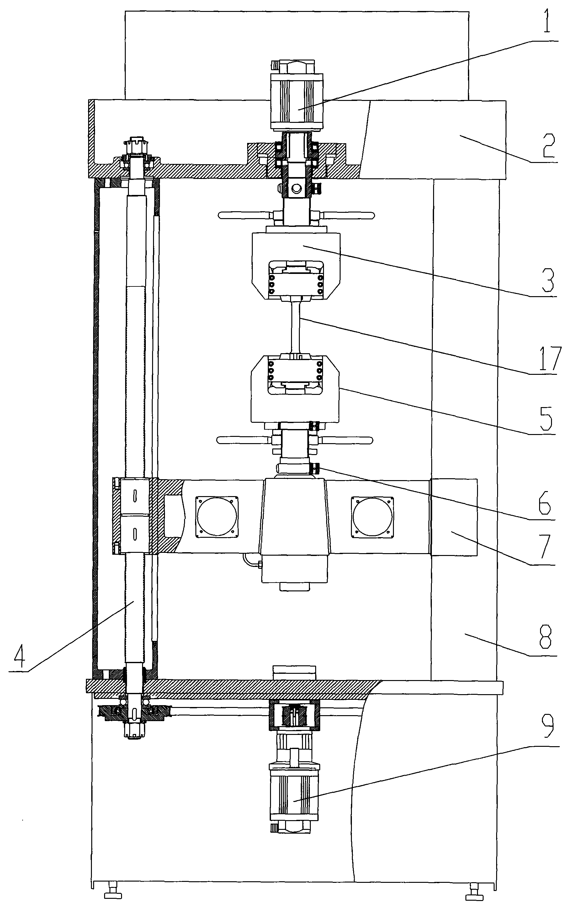
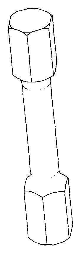
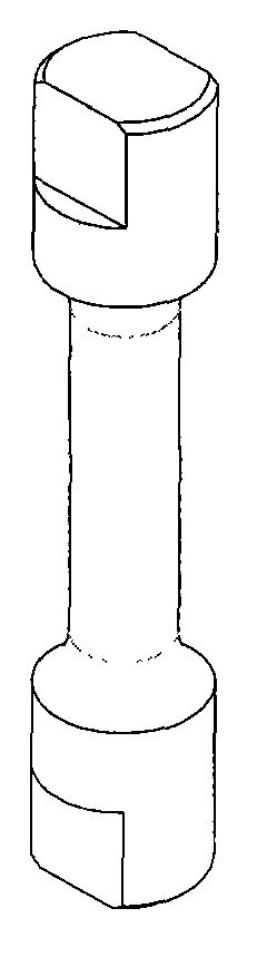
[0029] Example 1 as figure 1 , Figure 4 to Figure 9 , Figure 12 and Figure 13 As shown, a clamp for pulling and torsion test piece comprises an upper clamp 3, a lower clamp 5 and a pull and torsion test piece 17, and the upper clamp 3 and the lower clamp 5 are respectively provided with an upper jaw and a lower jaw, The upper clamping section 22 of the tensile and torsion test piece 17 is fixed by the upper jaw of the upper clamp 3, and the lower clamping section 23 of the tensile and torsion test piece 17 is fixed by the lower jaw of the lower clamp 5. The upper clamping section 22 of the test piece 17 is provided with an upper test piece keyway 19, the lower clamping section 23 is provided with a lower test piece keyway 21, and the upper jaw of the upper chuck 3 is provided with a corresponding keyway 19 for the upper test piece. The upper jaw keyway, the lower jaw of the lower chuck is provided with the lower jaw keyway corresponding to the lower test piece keyway 21...

Embodiment 2

[0032] Example 2 as Figure 10 , Figure 11 , Figure 14 and Figure 15 As shown, the upper test piece keyway 19 described in embodiment 2 is an upper test piece keyway, and the upper jaw is provided with a corresponding upper jaw keyway, and the upper test piece keyway and the upper jaw keyway are provided with key 18; the lower test piece keyway 21 is also a lower test piece keyway, and the lower jaw is also provided with a corresponding lower jaw keyway, and the lower test piece keyway and the corresponding lower jaw keyway are also equipped with key 18. Other structures of embodiment 2 are the same as embodiment 1.

[0033] When using the tension and twist test piece clamp of the present invention, release the handle 12, and the spring 14 bounces the limit block 26, so that the upper jaw (lower jaw) is opened, that is, the left half jaw and the right half jaw are separated left and right, and put in Pull and twist the test piece 17, hold the handle 12 to rotate the pr...


PUM


Abstract

The invention discloses a tension-torsion test specimen fixture, which comprises an upper chuck, a lower chuck and a tension-torsion test specimen, the upper chuck and the lower chuck are respectively provided with upper jaws and lower jaws, an upper clamped section of the tension-torsion test specimen is fixed by the upper jaws of the upper chuck, a lower clamped section of the tension-torsion test specimen is fixed by the lower jaws of the lower chuck, the upper clamped section of the tension-torsion test specimen is provided with upper test specimen key slots, the lower clamped section of the tension-torsion test specimen is provided with lower test specimen key slots, the upper jaws of the upper chuck are provided with upper jaw key slots corresponding to the upper test specimen key slots, the lower jaws of the lower chuck are provided with lower jaw key slots corresponding to the lower test specimen key slots, keys are mounted between the upper test specimen key slots and the upper jaw key slots, and keys are mounted between the lower test specimen key slots and the corresponding lower jaw key slots. The tension-torsion test specimen-clamping effect of the jaws of the tension-torsion test specimen fixture is good, the shapes of the clamped sections of the test specimen are not limited, the structure is simple, clamping does not need mechanical power, mechanical operation noise does not exist, the environment cannot be affected, and both the purchase cost and the use cost are low.

Description

technical field [0001] The invention relates to a tension-torsion testing machine, in particular to a test piece and a fixture in the tension-torsion testing machine, and belongs to the technical field of material mechanics testing machines. Background technique [0002] In the field of metal material mechanics experiments, the tensile torsion test is a new thing. The existing tensile torsion test torque is below 50N·m, which can be realized by ordinary tensile test chucks, but if the torque exceeds 200N·m, even When the torque reaches more than 1000N·m, it is easy to slip when the test piece is clamped by the chuck of the existing testing machine. The jaws for clamping metal materials are all made of hard materials and quenched. The contact surface between the jaws and the test piece is processed with various lines (such as straight lines, twill lines, cross lines and other non-slip tooth shapes). The pressure applied by the jaws to the specimen is very small, and when the...

Claims


Application Information

Patent Timeline
Patent Type & Authority Applications(China)
IPC IPC(8): G01N3/04
Inventor 孙芳山
Owner 烟台力尔自动化设备有限公司
Why Eureka
Try Eureka