Relay protection method for power supply circuit based on communication network

A technology for relay protection and power supply lines, applied in the direction of emergency protection circuit devices, electrical components, etc., can solve the problems of lack of power supply line protection, inability to accurately determine the position of line sections, tripping, etc., and achieve simplified relay protection control and protection The effect of the tuning method

Active Publication Date: 2011-09-14
北京广大泰祥自动化技术有限公司
View PDF4 Cites 10 Cited by
  • Summary
  • Abstract
  • Description
  • Claims
  • Application Information

AI Technical Summary

Problems solved by technology

Moreover, the amount of electrical data transmitted is large and the time period is long. Due to the influence of transmission line conditions, transmission methods, and power system fault interference, errors or interruptions will occur, resulting in protection failure or misoperation.
In addition, the structure of the protection device is complex, and the electrical quantity at both ends of the transmission line needs to be equipped with guide wires, high-frequency equipment, and microwave equipment, and the investment in equipment is large, so it is only used on important high-voltage and ultra-high-voltage lines at present.
[0005] Therefore, the existing power supply line relay protection methods and protection devices cannot accurately determine the location of the line section where the fault occurs, thereby determining the protection range and protection mode of the relay protection device, resulting in the lack of protection of the power supply line and the tripping of the over-level maloperation protection

Method used


Image

  • Relay protection method for power supply circuit based on communication network
  • Relay protection method for power supply circuit based on communication network
  • Relay protection method for power supply circuit based on communication network

Examples


Embodiment Construction

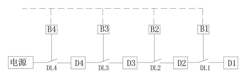
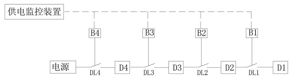
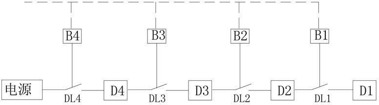
[0018] The communication network-based relay protection method for power supply lines in the present invention firstly divides the power supply section from the power supply outlet end to the end of the power supply line; the power supply line is located between two circuit breakers to form a power supply section. Such as figure 1 As shown, the load D1 carried by the end circuit breaker DL1 is a first-level power supply section. When a fault occurs at point D1, the relay protection devices B1, B2, B3, and B4 all detect fault data, and the relay protection device B1 passes the wired or The wireless communication network sends fault signals with identification codes (address codes) to relay protection devices B2, B3, and B4, and relay protection device B2 sends fault signals with identification codes (address codes) to relay protection devices B3 and B4. fault signal, the relay protection device B3 sends a fault signal with an identification code (address code) to the relay prot...


PUM


Abstract

The invention discloses a relay protection method for a power supply circuit based on a communication network. The method comprises the following steps of: partitioning power supply sections from the power supply outlet end to the tail end of the power supply circuit, wherein a power supply section is formed between two circuit breakers on the power supply circuit, and a section controlled by a circuit breaker positioned at the tail end of the power supply circuit serves as a primary power supply section; realizing communication junction of the communication interface of a relay protection device of the circuit breaker in each partitioned power supply section through a wireless network; making each relay protection device transmit a detected fault signal with an identification code to the relay protection device in each power supply section close to the power supply outlet end respectively through a network; and making the relay protection device which receives the fault signal determine the position of the relay protection device which transmits the fault signal according to the identification code of the fault signal respectively and determine a failed power supply section according to the position of the relay protection device which is furthest away from the power supply outlet end. By adopting the method, the relay protection control and protection setting of the power supply circuit are simplified.

Description

technical field [0001] The invention relates to a power supply line relay protection system, in particular to a communication network-based power supply line relay protection method. Background technique [0002] At present, there are two types of relay protection methods for power supply lines in existing relay protection systems: 1. Current and voltage protection and distance protection, which determine the protection range and action mode according to the change of electrical quantity at one end of the line; The longitudinal differential protection, high frequency protection, and microwave protection determine the protection range and action mode according to the quantity change. The protection principle is that when the power supply line fails, the protection range and protection mode are determined by comparing the change value of the line electrical quantity by the relay protection device, and different protection action modes and action sequences are adopted according...

Claims


Application Information

Patent Timeline
Patent Type & Authority Applications(China)
IPC IPC(8): H02H7/26
Inventor 吴登庆
Owner 北京广大泰祥自动化技术有限公司
Why Eureka
Try Eureka