Electromagnetic regulator

A technology for adjusting equipment and electromagnetism. It is applied to electromagnets, mechanical equipment, electromagnets with armatures, etc. It can solve problems such as shortening lifespan, and achieve the effects of reducing friction, unobstructed rotation, and reducing material wear.

Active Publication Date: 2011-09-14
ETO MAGNETIC GMBH
View PDF2 Cites 5 Cited by
  • Summary
  • Abstract
  • Description
  • Claims
  • Application Information

AI Technical Summary

Problems solved by technology

Nevertheless, it has been shown in practice that the aforementioned unavoidable misalignment of the axis between the adjustment partner and the plunger unit leads to a significant reduction in the lifespan

Method used


Image

  • Electromagnetic regulator
  • Electromagnetic regulator

Examples


Embodiment Construction

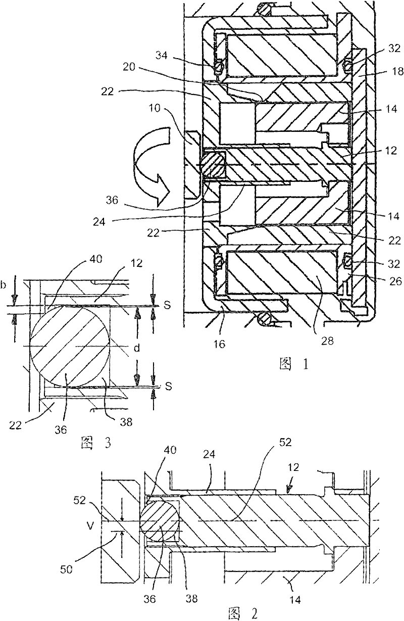
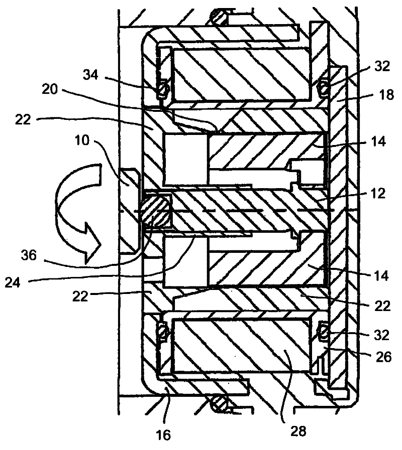
[0018] figure 1 The principle structure and the periphery of an electromagnetic adjusting device according to a first preferred embodiment, which is mounted via a camshaft adjustment of an internal combustion engine shown only schematically in section ( Not shown) pressure on the valve slide 10 of the switching valve unit to adjust the camshaft.

[0019] Linear thrust (at figure 1 Axial to the left in the drawing) is applied to the valve slide unit 10 by the plunger unit 12, which is part of the armature unit of the electromagnetic adjustment device shown and is connected to the cup-shaped armature The parts 14 cooperate to form an armature unit movably guided inside a two-piece housing made of a housing shell 16 and a housing bottom 18 . Strictly speaking, the armature units 12, 14 are surrounded by a yoke core unit 22 in this embodiment, which is integrally formed with a centrally located, conically tapering on both sides, in order to form a magnetic circuit. The middle p...


PUM


Abstract

The invention relates to an electromagnetic regulator comprising an armature unit with a plunger unit (12) carrying out a linear movement when energised by a current flowing in a stationary coil unit (26, 38), wherein the plunger unit is designed to cooperate at the end thereof with a regulator partner (10). According to the invention, the plunger unit has a slide or ball bearing (36) at the end thereof which is fixed in a cage-like housing (38, 40) on the plunger unit such as to be able to rotate such as to be able to rotate in reaction to a frictional force at right angles to the direction of the linear regulation movement.

Description

technical field [0001] The invention relates to an electromagnetic adjustment device according to the preambles of the independent claims. Such devices are generally known in the prior art and are generally used for actuating (switching) valves, wherein an electromagnetically driven armature unit of the described type is combined with a valve slide or similar structure of such a switching valve as an adjustment partner The units cooperate in order to apply the adjustment force through a linear adjustment movement. Background technique [0002] A specific such known hypothetical use case is the adjustment of a camshaft of an internal combustion engine. Such a regulating device acts here as a pressure valve in an axial position relative to the camshaft of the motor. In this case, the vertically mounted adjusting device contacts the valve with the end face of the plunger unit, which acts to adjust the camshaft. [0003] Manufacturing tolerances, thermally dependent influence...

Claims


Application Information

Patent Timeline
Patent Type & Authority Applications(China)
IPC IPC(8): H01F7/16
CPCH01F2007/085F16K31/06H01F7/1607H01F2007/086H01F2007/083
Inventor 斯蒂芬·本德
Owner ETO MAGNETIC GMBH
Why Eureka
Try Eureka