Acoustic power measuring frame

A technology for measuring racks and sound power, applied to measuring devices, measuring ultrasonic/sonic waves/infrasonic waves, instruments, etc., can solve problems such as installation and transportation of sound power measuring racks, and reduce manufacturing costs of sound power measuring racks

Inactive Publication Date: 2011-09-21
上海声望声学科技股份有限公司
View PDF0 Cites 3 Cited by
  • Summary
  • Abstract
  • Description
  • Claims
  • Application Information

AI Technical Summary

Problems solved by technology

[0007] The object of the present invention is to provide a sound power measuring frame to solve the problem of difficult installation

Method used


Image

  • Acoustic power measuring frame
  • Acoustic power measuring frame
  • Acoustic power measuring frame

Examples


Embodiment 1

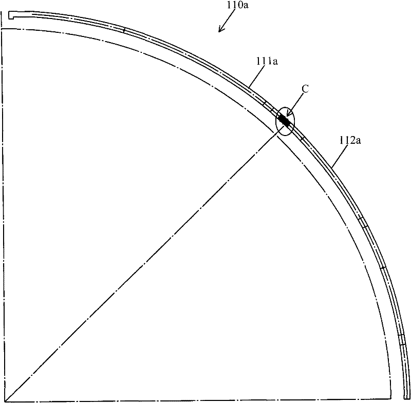
[0026] Please refer to Figure 3 to Figure 6 ,in image 3 It is a structural schematic diagram of the support guide rail of the sound power measurement stand provided by Embodiment 1 of the present invention; Figure 4 and Figure 5 respectively image 3 An enlarged schematic diagram of the connecting ends of the two connecting segments, wherein (a) is a cross-sectional view, and (b) is a view in the direction of A-A; Figure 6 An enlarged schematic illustration of the assembly of the connected ends of two connected segments together.

[0027] As shown in the figure, the bracket rail 110a includes a first connecting section 111a and a second connecting section 112a. Wherein the connection end C1 of the first connection section 111a has a slot C11 (such as Figure 4 ), the connecting end C2 of the second connecting section 112a is an insert structure (such as Figure 5 ) to insert into slot C11. In addition, there are corresponding positioning holes C3 and C4 on the sock...

Embodiment 2

[0033] Please refer to Figure 7 , which is a structural schematic diagram of the support guide rail of the sound power measurement stand provided in Embodiment 2 of the present invention. It can be seen from the figure that it is different from Embodiment 1 in that the two adjacent connecting sections are pivoted, that is, the two adjacent connecting sections can be folded.

[0034] Specifically, as shown in the figure, the two connecting sections 111b and 112b of the bracket guide rail 110b are pivotally connected to each other, so that the connecting section 112b can rotate around the connecting point D toward the connecting section 111b. In this way, when the sound power measurement stand is not in use, the stand rails can be folded for storage or transportation to save space.


PUM


Abstract

The invention discloses an acoustic power measuring frame which comprises multiple arc bracket guide rails. The arc bracket guide rails are connected at one end and are entirely in a partial-spherical shape, wherein each bracket guide rail comprises multiple arc connection sections in movable connection. The bracket guide rail of the acoustic power measuring frame is formed by connecting multiple arc connection sections in a movable mode; and thus, in the transportation process, each connection section of the bracket guide rail can be removed, the space taken by the whole is reduced, and the transportation is convenient. Moreover, in the manufacturing process of the acoustic power measuring frame, the processing can be performed by section, the size of the required plate is relatively small, the processing precision is easier to control, the plate waste is greatly reduced, and the manufacturing cost is lowered.

Description

technical field [0001] The invention relates to the technical field of sound power measurement, in particular to a sound power measurement frame. Background technique [0002] Sound power measurement is widely used in various fields such as automobiles, aerospace, home appliances, computers and communications, and industrial products for noise measurement and acoustic characteristic measurement of products. A relatively common sound power measurement method is the free field method, that is, the sound source is placed in a free sound field (for example, an anechoic chamber), and the measurement is made on a hemispherical surface centered on the sound source or other measurement surfaces with certain symmetry. (such as semi-cylindrical, rectangular hexahedron, etc.) on the sound pressure level of several uniformly distributed points, and then obtain the sound power level. [0003] Please refer to figure 1 , which is a schematic configuration diagram of an existing sound pow...

Claims


Application Information

Patent Timeline
IPC IPC(8): G01H17/00
Inventor 罗伟
Owner 上海声望声学科技股份有限公司
Why Eureka
Try Eureka