Blood pressure measuring apparatus

A technology for measuring device and blood pressure, which can be used in vascular assessment, cardiac catheterization, etc., and can solve the problems of complex mechanism and poor usability

Active Publication Date: 2011-09-21
OMRON HEALTHCARE CO LTD
View PDF6 Cites 8 Cited by
  • Summary
  • Abstract
  • Description
  • Claims
  • Application Information

AI Technical Summary

Problems solved by technology

[0010] The problem to be solved by the present invention is that the mechanism of the device is complicated when the cuff is automatically wound to the winding size (winding circumference) of the measured object part, and the cuff winding structure utilizing hand power The problem of poor usability for people with finger disabilities

Method used


Image

  • Blood pressure measuring apparatus
  • Blood pressure measuring apparatus
  • Blood pressure measuring apparatus

Examples


no. 1 approach

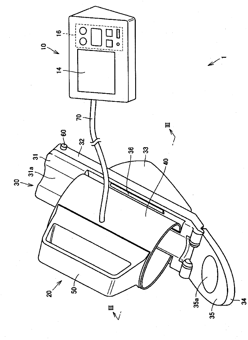
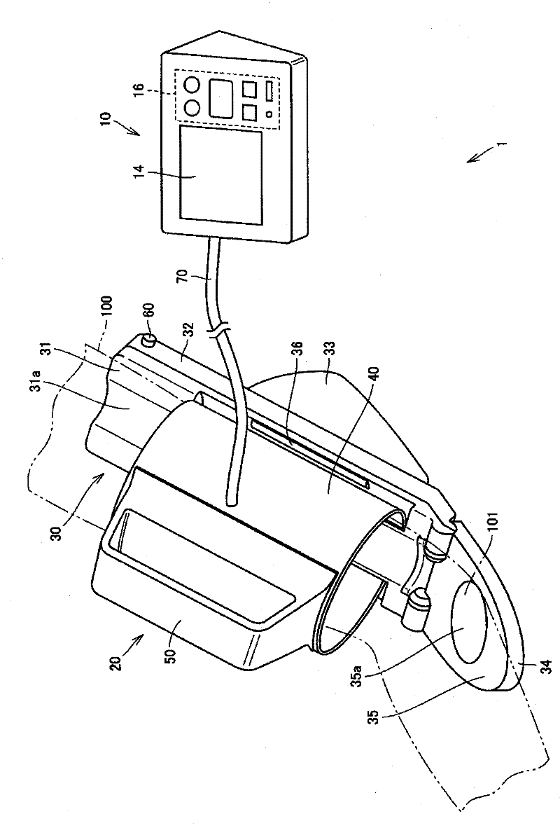
[0042] refer to figure 1 and figure 2 The external configuration of the blood pressure measurement device 1 of the first embodiment will be described. in addition, figure 1 It is a figure showing the appearance structure of the blood pressure measuring device 1 of this embodiment, figure 2 It is a diagram showing an appearance structure showing a state where the upper arm is attached to the blood pressure measurement device 1 of the present embodiment.

[0043] like figure 1 and figure 2 As shown, the blood pressure measurement device 1 of this embodiment has a main body 10 , a cuff 20 and an air tube 70 . The main body 10 is used by being placed on a placement surface such as a desk during measurement, and has a display unit 14 and an operation unit 16 on the upper surface. The cuff 20 is used on the upper arm in a state of being placed on a placing surface such as a desk during measurement, and includes an upper arm support stand 30 and a cuff main body 40 .

[004...

no. 2 approach

[0065] Next, refer to Figure 10 to Figure 16 , the blood pressure measurement device 2 according to the second embodiment of the present invention will be described. in addition, Figure 10 It is a figure showing the internal structure of the blood pressure measurement device 2 of this embodiment, Figure 11 is a schematic diagram showing a control block diagram of the blood pressure measurement device 2 according to this embodiment, Figure 12 It is a diagram showing the flow of blood pressure measurement by the blood pressure measurement device 2 according to the second embodiment of the present invention.

[0066] in addition, Figure 13 It is the first graph showing the relationship between stroke and pressure when measuring blood pressure, Figure 14 It is a first cross-sectional schematic diagram showing a tightened state of the upper arm 100 of the blood pressure measurement device 2 of the second embodiment during blood pressure measurement, Figure 15 is the sec...

no. 3 approach

[0079] Next, refer to Figure 17 to Figure 21 A blood pressure measurement device 3 according to a third embodiment of the present invention will be described. in addition, Figure 17 It is a figure showing the appearance structure of the blood pressure measurement device 3 of this embodiment, Figure 18 It is a diagram showing the configuration of the cuff 300 of the blood pressure measurement device 3 according to the present embodiment. in addition, Figure 19 is along Figure 18 Sectional view of section XIX-XIX in, Figure 20 is a schematic plan view showing the rotation mechanism including the engaging rotation member of the blood pressure measurement device 3 according to the present embodiment, Figure 21 It is a block diagram of the blood pressure measurement device 3 of this embodiment.

[0080] like Figure 17 As shown, the blood pressure measurement device 3 of this embodiment has a main body 10 , a cuff 300 , an air tube 70 and a connection cable 71 . The ...


PUM


Abstract

Provided is a blood pressure measuring apparatus wherein a rotating shaft (47) rotates clockwise when a force is applied to one end side (40a) and the other end side (40b) of a cuff main body section (40) in a direction of further reducing the inner diameter of a cylindrical form, and the end side (40a) and the other end side (40b) of the cuff main body section (40) are moved at the same time. As a result, the inner diameter of the cylindrical form of the cuff main body section (40) can be reduced only by a pressing operation with one hand, and the cuff main body section (40) can be easily and quickly wound on an upper arm (100). Thus, the blood pressure measuring apparatus which has the simple configuration and allows even a person having problems with hands to easily wind the cuff on an area to be measured is provided.

Description

technical field [0001] The present invention relates to a blood pressure measurement device which wraps a cuff around an arm to measure blood pressure. Background technique [0002] When measuring blood pressure, an air bag is wound to compress the arteries of the human body to be measured (upper arm, wrist, thigh, ankle), binds and fixes the air bag from the surroundings, and adds and subtracts the air bag pressure to measure blood pressure. [0003] Japanese Unexamined Patent Publication No. 2005-230175 (Patent Document 1) discloses a blood pressure measurement device having an automatic cuff winding mechanism. In addition, JP-A-2008-054867 (Patent Document 2) discloses a blood pressure measurement device that wraps a cuff around an upper arm using hand power. In any of the blood pressure measuring devices, air is fed into an air bag provided inside the cuff, and the upper arm is pressed to measure the blood pressure. [0004] However, in the blood pressure measurement ...

Claims


Application Information

Patent Timeline
Patent Type & Authority Applications(China)
IPC IPC(8): A61B5/022
CPCA61B5/02141A61B5/02233
Inventor 谷口实渡边庸一郎王兰兰野吕裕一
Owner OMRON HEALTHCARE CO LTD
Why Eureka
Try Eureka