Electric pressurization outpouring type liquid container

A liquid container, electric technology, used in non-pressure containers, gas/liquid distribution and storage, cooking utensils, etc., can solve the problems of reduced injection volume, easy air leakage, injection, etc., to achieve stable injection volume, reduce water effect

Active Publication Date: 2011-09-28
THERMOS CHINA HOUSEWARES
View PDF6 Cites 2 Cited by
  • Summary
  • Abstract
  • Description
  • Claims
  • Application Information

AI Technical Summary

Problems solved by technology

[0004] In the prior art, when the steam in the container main body is discharged and the air pump is operated to supply air into the container main body, the steam discharge hole of the cover body and the air injection port of the middle plug are used in any case of the above-mentioned steam and air, When the switch operation part is operated, the above-mentioned steam and air collide with the steam discharge hole of the cover body and the air injection port of the middle plug, and hot water may not be poured out smoothly.
[0005] In addition, the method in the prior art is to inject air into the container when pouring out to pour out the content

Method used


Image

  • Electric pressurization outpouring type liquid container
  • Electric pressurization outpouring type liquid container
  • Electric pressurization outpouring type liquid container

Examples


Embodiment 1

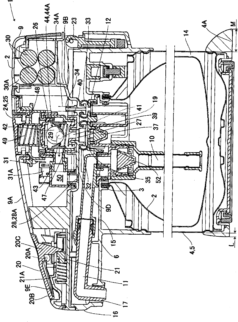
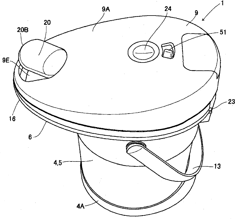
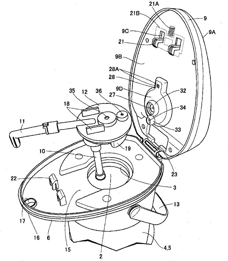
[0030] Figure 1 to Figure 10 Showing Embodiment 1, an electric kettle 1 is provided with: a container main body 5 having a bottomed inner tube 2 for accommodating liquids such as water; A bottomed outer cylinder 4 that is also used as an exterior; a substantially horizontal and substantially disc-shaped shoulder member 6, which is also called a water removal member, etc., is combined to form the outer peripheral upper end side of the outer cylinder 4 and the container body 5. The mouth 3 is covered; the hollow cover body 9 is provided with an electric diaphragm (not shown) air pump, that is, an electric pump 8, and is installed on the upper surface of the shoulder member 6 in a freely openable and closed manner; the middle plug 12, which is provided with a water pipe 10 for discharging the liquid in the inner cylinder 2 at the upper part, and is equipped with a water injection pipe 11 communicated with the water pipe 10 at the upper part, and seals the mouth 3 detachably; and...

Embodiment 2

[0063] Next, other examples will be described. However, the same reference numerals are assigned to the same parts as those in the first embodiment described above, and detailed description thereof will be omitted.

[0064] Figure 11 Example 2 is shown. In Example 2, the sealing members 32 and 33 of Example 1 are used together, and exhaust leakage and air leakage are provided on the lower surface of the cover 9 so as to surround the steam hole 27 and the exhaust hole 34 on the cover 12 side. The sealing member 32' serving as a leak prevention seal member 32' encloses the middle plug exhaust gas and the middle plug air which are also used as the middle plug exhaust path 35 and the middle plug air supply path 36 in the first embodiment. It is sent into the upper end of the dual-purpose road 35', and is arranged on the upper surface of the middle plug 12; the steam can be discharged through the middle plug exhaust and the middle plug air into the dual-purpose road 35', the seal...

Embodiment 3

[0066] Figure 12 Example 3 is shown, and the steam hole 27 on the side of the cover body 9 of Example 1, the lower end opening 27' of the exhaust hole 34 and the lower end opening 27' of the exhaust hole 34 are provided on the cover body so as to surround the lower end opening portion 27'. The lower surface of 9 is provided with exhaust leakage and air leakage preventing dual-purpose sealing member 32 ", and the inner side surrounded by the lower end of this sealing member 32 " will double as the middle plug exhaust passage 35 and the middle plug air of Embodiment 1 into The middle plug exhaust and the middle plug air of the road 36 are sent to the upper end of the double-purpose road 35 ′, and are arranged on the upper surface of the middle plug 12, and the steam can be sent into the double-purpose road 35 ′ and the sealing member 32 through the middle plug exhaust and the middle plug air. ", the lower end opening 27', and the steam hole 27 are discharged, and on the other h...


PUM


Abstract

The invention relates to an electric pressurization outpouring type liquid container, which reduces a sealing component, decreases the unevenness of force applied on the sealing component due to the inclination or shake of a cover body and makes it hard for air in a container body to leak. A middle bolt capable of free dismounting is disposed in the container body, and a middle bolt air feeding path for the air from a pump and a middle bolt discharging path for air in the container are disposed in the middle bolt. A sealing component is disposed in the cover body. The sealing component is disposed between a vapor hole and the middle bolt discharging path and is used for preventing exhaust air from leakage. The sealing component is clamped between a discharging hole and the middle bolt air feeding path and is used for preventing air from leakage. Through reducing the sealing component, the unevenness of force applied on the sealing component due to the inclination or shake of the cover body is reduced and air in the container body is hard to leak out. At the time of outpouring operation, the outpouring amount will not be reduced and will be stable.

Description

technical field [0001] The present invention relates to an electric pressurization and pouring type liquid container such as an electric kettle (air pot). Background technique [0002] In the past, as this type of container, a middle stopper is provided on the upper part of the container main body that accommodates the content liquid, a water discharge pipe is provided at the lower part of the middle stopper, an outlet communicating with the water discharge pipe is provided at the top of the middle stopper, and further, A hollow is formed on the lower surface of the cover above the plug, so that the outlet of the air pump arranged in the cover communicates with the container main body through the hollow, and a steam discharge hole communicating with the atmosphere is formed in the hollow, and the steam discharge hole is set. On the other hand, the on-off valve for opening and closing is provided on the operating lever for operating the on-off valve. After operating the opera...

Claims


Application Information

Patent Timeline
IPC IPC(8): A47J27/21A47J36/00A47J41/02
Inventor 渡边利行村上靖浩木暮刚
Owner THERMOS CHINA HOUSEWARES
Why Eureka
Try Eureka