Method and device for debugging optical power

A debugging device and optical power technology, applied in the field of communication, can solve the problems of communication information occupying a certain amount of time, time-consuming, etc., and achieve the effect of improving network communication performance and saving time

A debugging device and optical power technology, applied in the field of communication, can solve the problems of communication information occupying a certain amount of time, time-consuming, etc., and achieve the effect of improving network communication performance and saving time

CN102201863AInactive Publication Date: 2011-09-28HUAWEI TECH CO LTD

Image

  • Method and device for debugging optical power
  • Method and device for debugging optical power
  • Method and device for debugging optical power

Examples


Embodiment Construction

[0030] The following will clearly and completely describe the technical solutions in the embodiments of the present invention with reference to the drawings in the embodiments of the present invention.

[0031] It should be clear that the described embodiments are only some of the embodiments of the present invention, not all of them. Based on the embodiments of the present invention, all other embodiments obtained by persons of ordinary skill in the art without making creative efforts belong to the protection scope of the present invention.

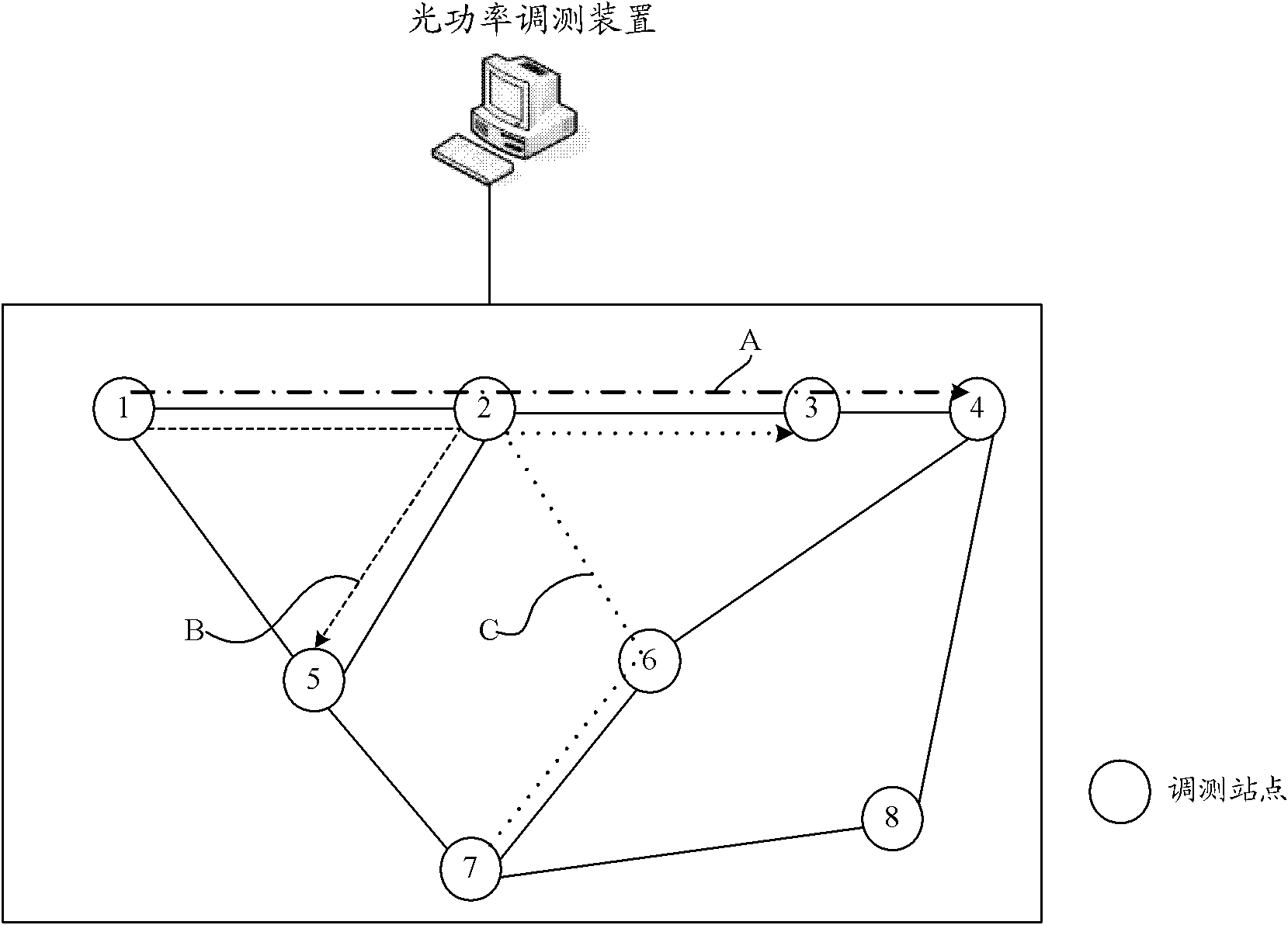
[0032] It should be noted that the optical power commissioning method provided by the embodiment of the present invention is applied to a wavelength division network, and the wavelength division network includes at least one network site and is configured with a An optical power commissioning device for optical power commissioning of a network site, such as a special commissioning tool, in the embodiment of the present invention, the net...


PUM


Abstract

The embodiment of the invention provides a method and device for debugging optical power, relates to the technical field of communications and is used for effectively saving debugging time. The method comprises the following steps: determining the regulating information and debugging sequence of each debugging station; and sending the corresponding regulating information and the debugging sequence information to each debugging station respectively, wherein the debugging sequence information corresponding to the debugging station indicates a preposed debugging station and a follow-up debugging station of the debugging station, thus each debugging station debugs the optical power in accordance with the regulating information and the debugging sequence corresponding to the debugging station. The method and device can be applied to wavelength division networks.

Description

technical field [0001] The present invention relates to the field of communication technology, in particular to an optical power commissioning method and device. Background technique [0002] Wavelength division network is an optical network that adopts the principle of wavelength division multiplexing transmission. Wavelength division multiplexing transmission means that at the transmitting end of the optical network, different optical signals are carried by different wavelengths or frequencies, and then multiplexed to one optical fiber for transmission. to the receiving end. In the WDM network, as the transmission distance increases, the service signal power will gradually decrease. Therefore, in the existing network, an optical amplifier (optical amplifier for short) OA (Optical Amplifier) ​​board will be placed at intervals to The business signal is amplified. However, since a certain amount of noise is gradually generated during signal transmission, the OA board will ...

Claims


Application Information

Patent Timeline
28 Sep 2011
Publication
CN102201863A
IPC
H04B10/08; H04B10/12; H04B10/07
Inventors
石礌; 徐明明