Continuous extrusion device

A technology of extrusion equipment and extrusion wheel, which is applied in the direction of metal extrusion dies, etc., can solve the problems of long billet runner, huge equipment, and low yield, and achieve the goals of avoiding depressions and cracks, improving product quality, and increasing output Effect

Active Publication Date: 2011-10-05
HEFEI SMARTER TECH GROUP CORP
View PDF5 Cites 2 Cited by
  • Summary
  • Abstract
  • Description
  • Claims
  • Application Information

AI Technical Summary

Problems solved by technology

[0003] At present, due to the large diameter of the metal outer sheath of the ultra-high voltage cable, it is generally formed by welding a metal strip, that is, seam welding. The material grains at the welding place of this welding method are coarse and uneven, which affects the electrical and electrical properties of the cable. mechanical physical properties
The continuous aluminum pressing machine produced with aluminum ingots is huge in equipment, high in energy consumption, complex in structure, and expensive in cost, while traditional continuous continuous extrusion equipment has a structure of single wheel and single groove or single wheel and double groove, which is relatively simple , because this equipment has only one runner, and its extrusion chamber has only one hole communicating with it, so the flow path of the billet in the extrusion chamber is long, resulting in a large temperature difference between the upper and lower sides, and the product qualification rate is low. This kind of single wheel, single groove or single The double groove structure of the wheel usually can only produce products with small diameter and small cross section. It is very difficult to produce products with large diameter and the yield is low.

Method used


Image

  • Continuous extrusion device
  • Continuous extrusion device
  • Continuous extrusion device

Examples


Embodiment Construction

[0019] The present invention will be further described below in conjunction with accompanying drawing:

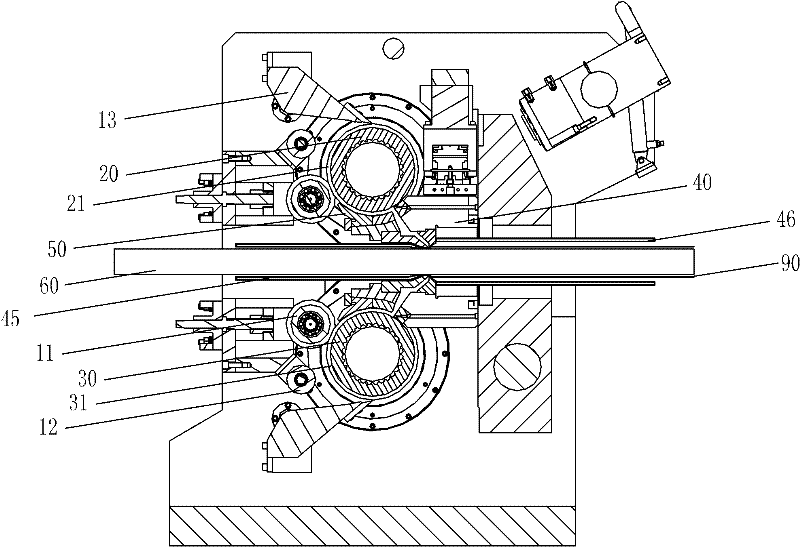
[0020] The continuous extrusion equipment includes a frame 10, which is in the shape of a torii, and two extrusion wheels 20, 30 whose rotating shafts are parallel to each other are arranged on the frame 10. As a preferred solution of the present invention, the extrusion wheels 20, 30 are selected to be arranged The upper and lower structures are arranged in parallel, and the following instructions are also described with the upper and lower parallel structures.

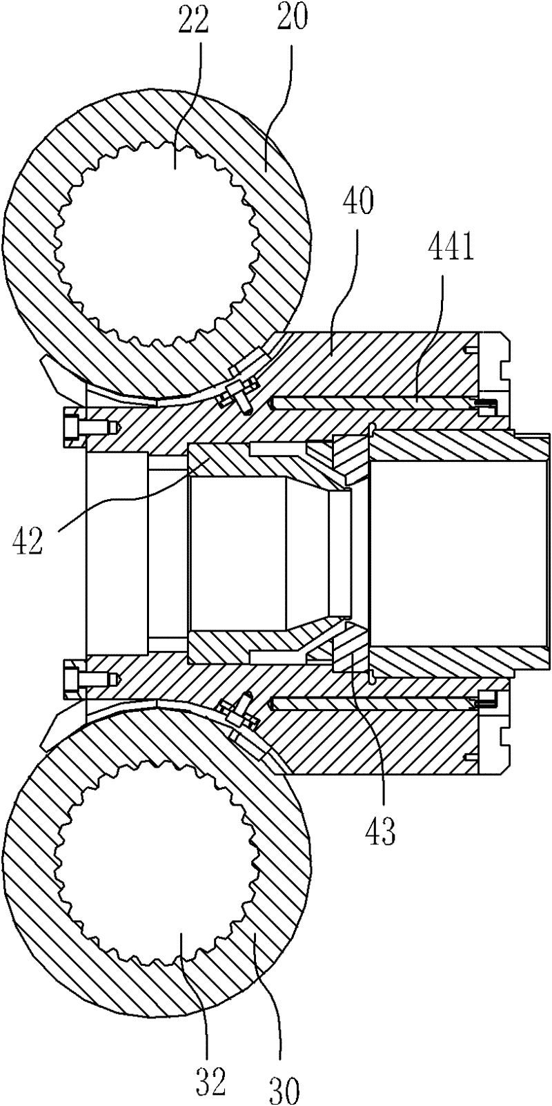
[0021] Such as figure 1 , Figure 5 As shown, the rotating shafts 22, 32 of the extrusion wheels 20, 30 are arranged in parallel up and down, the direction of rotation of the extrusion wheels 20, 30 is opposite, and the rims are respectively provided with at least one extrusion wheel groove 21, 31 in the circumferential direction, The extrusion wheel grooves 21, 31 are respectively provided with a guide seat 50 ...


PUM


Abstract

The invention relates to a continuous extrusion device. A stand of the continuous extrusion device is provided with two extruding wheels with mutually-parallel rotating shafts, rotation directions of the extruding wheels are opposite and rims are respectively provided with at least one extruding wheel groove in the circumference direction, guide seats matched with the extruding wheel grooves are respectively arranged on the extruding wheel grooves, the guide seats and the extruding wheel grooves form an extruding cavity through which blanks pass, a die holder is arranged between the extrudingwheels, a channel through which a cable passes is arranged inside the die holder, two sides of a die holder shaft core line are symmetrically provided with holes communicated with the extruding cavity along the radial direction, the holes are communicated with a wrapping cavity of the die holder, and an outlet of the wrapping cavity is wrapped on the periphery of the outlet end of the cable in the channel. The extruding blanks enter the extruding cavity and then enter the wrapping cavity through the holes on the die holder. Because the holes are symmetrically arranged in the radial direction of the die holder, the extruding blanks simultaneously enter the wrapping cavity at the upper position and the lower position of the die holder, and a runner of the blanks is shortened; and temperature difference is little and the blanks flowing through the die holder are sufficient, and thus the yield is increased.

Description

[0001] The present invention is a divisional application of an invention patent with an application date of July 8, 2009, an application number of 200910144064.8, and an invention title of "extrusion machine". technical field [0002] The invention relates to a continuous extrusion equipment, in particular to an extrusion equipment for forming metal by continuous extrusion. Background technique [0003] At present, due to the large diameter of the metal outer sheath of the ultra-high voltage cable, it is generally formed by welding a metal strip, that is, seam welding. The material grains at the welding place of this welding method are coarse and uneven, which affects the electrical and electrical properties of the cable. mechanical physical properties. The continuous aluminum pressing machine produced with aluminum ingots is huge in equipment, high in energy consumption, complex in structure, and expensive in cost, while traditional continuous continuous extrusion equipment...

Claims


Application Information

Patent Timeline
Patent Type & Authority Applications(China)
IPC IPC(8): B21C23/21B21C25/02
Inventor 岳光明陈学模向晓红
Owner HEFEI SMARTER TECH GROUP CORP
Why Eureka
Try Eureka