Supercharge Your Innovation With Domain-Expert AI Agents!

Steel piece hot scarfing device and nozzle clogging detection method thereof

A technology of flame cleaning and blockage detection, which is applied in combustion methods, gas flame welding equipment, lighting and heating equipment, etc., and can solve problems such as the influence of steel billet flame cleaning quality

Active Publication Date: 2014-06-18
NIPPON STEEL CORP
View PDF9 Cites 0 Cited by
  • Summary
  • Abstract
  • Description
  • Claims
  • Application Information

AI Technical Summary

Problems solved by technology

In particular, if nozzle clogging occurs at the protective fuel gas nozzle, it will greatly affect the quality of the billet flame cleaning

Method used


Image

  • Steel piece hot scarfing device and nozzle clogging detection method thereof
  • Steel piece hot scarfing device and nozzle clogging detection method thereof
  • Steel piece hot scarfing device and nozzle clogging detection method thereof

Examples


Embodiment Construction

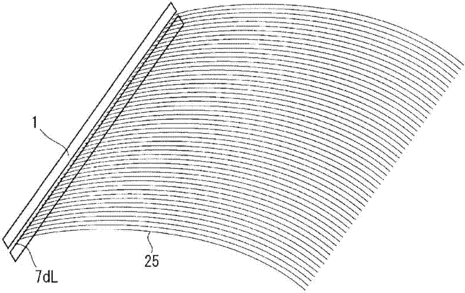
[0041] The inventors of the present application found that water is supplied to the shielding fuel gas cylinder of the flame cleaning mechanism, and the water is sprayed from the shielding fuel gas nozzle, and nozzle clogging can be detected based on the spraying state. That is, if Figure 2B As shown in FIG. 2 , the jetting state of water jetted from nozzles with clogged nozzles is different, so that clogged nozzles can be found at a glance.

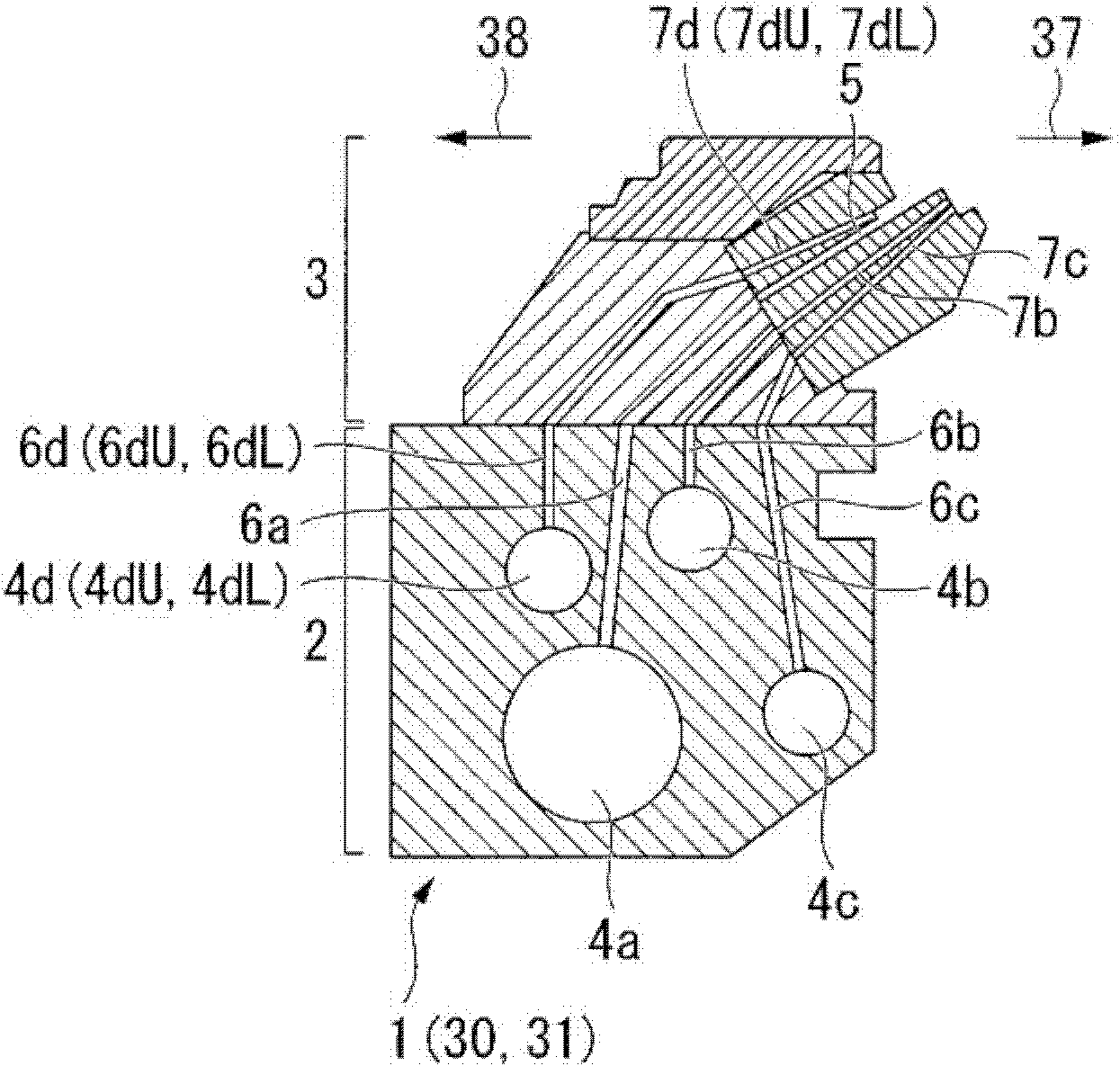
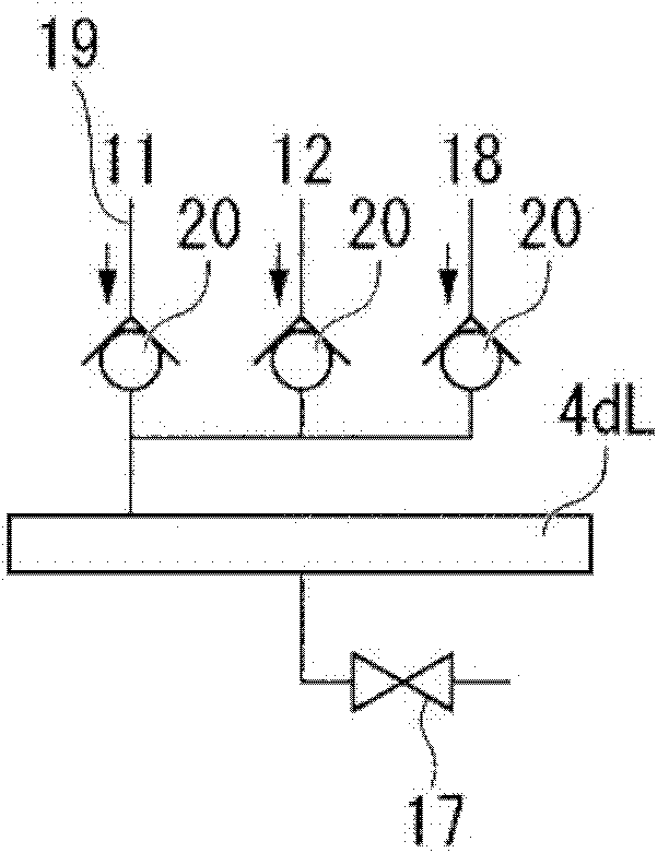
[0042] However, the flame cleaning device for steel slabs has: a pressure detection device for detecting the pressure in each gas cylinder in each flame cleaning mechanism; and a pressure detection tube connected between each gas cylinder and each pressure detection device. In this way, the flame cleaning device is designed so that the pressure in each gas cylinder can be detected by the pressure detection device.

[0043] Therefore, when water is supplied to the guard fuel gas cylinder, the water will infiltrate into the above-mention...


PUM


Abstract

The steel piece hot scarfing device is equipped with a lower shield fuel gas nozzle for spraying a shield fuel gas to the bottom surface of a steel piece, a lower shield fuel gas cylinder for supplying the shield fuel gas to the lower shield fuel gas nozzle, a fuel gas supply system for supplying the shield fuel gas to the lower shield fuel gas cylinder, and a water supply system for supplying water to the lower shield fuel gas cylinder.

Description

technical field [0001] The invention relates to a flame cleaning device for a billet and a method for detecting blockage of a nozzle thereof. This flame cleaning device has a torch for blowing oxygen to the surface of the billet. [0002] This application is based on and claims priority to Patent Application No. 2008-290938 filed in Japan on November 13, 2008, and the content thereof is incorporated herein. Background technique [0003] In order to improve the quality by removing cracks, surface matter, pores, etc. that exist near the surface of billets produced by continuous casting, etc., the surface is flame cleaned by blowing oxygen to the billets under hot conditions. This process of flame scarfing under hot conditions is also referred to as a hot scarf process. The four surfaces (upper surface, lower surface, and both sides) are flame-cleaned simultaneously under hot conditions, so the quality of the billet can be improved at high speed, high efficiency, and low cost...

Claims


Application Information

Patent Timeline
Patent Type & Authority Patents(China)
IPC IPC(8): B23K7/06B22D11/126
CPCF23C2900/07022F23D14/52B22D11/1265B23K7/06F23D14/42F23D14/22B22D11/16B22D11/1213
Inventor 细川正三郎山中秀一
Owner NIPPON STEEL CORP
Features
  • R&D
  • Intellectual Property
  • Life Sciences
  • Materials
  • Tech Scout
  • Unparalleled Data Quality
  • Higher Quality Content
  • 60% Fewer Hallucinations
Learn More