
An electric machine

A technology of rotating electrical machines and linear motors, applied in the field of permanent magnet motors, can solve problems such as low efficiency

Inactive Publication Date: 2014-07-23
钱蒂 森格钱
View PDF6 Cites 0 Cited by
  • Summary
  • Abstract
  • Description
  • Claims
  • Application Information

AI Technical Summary

Problems solved by technology

Existing electric motors may have inefficient control circuits and processes that provide power to the power coils that generate the dynamic magnetic field, especially at higher operating frequencies

Method used


Image

  • An electric machine
  • An electric machine
  • An electric machine

Examples


Embodiment Construction

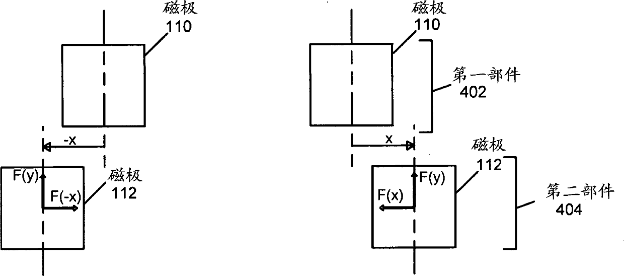
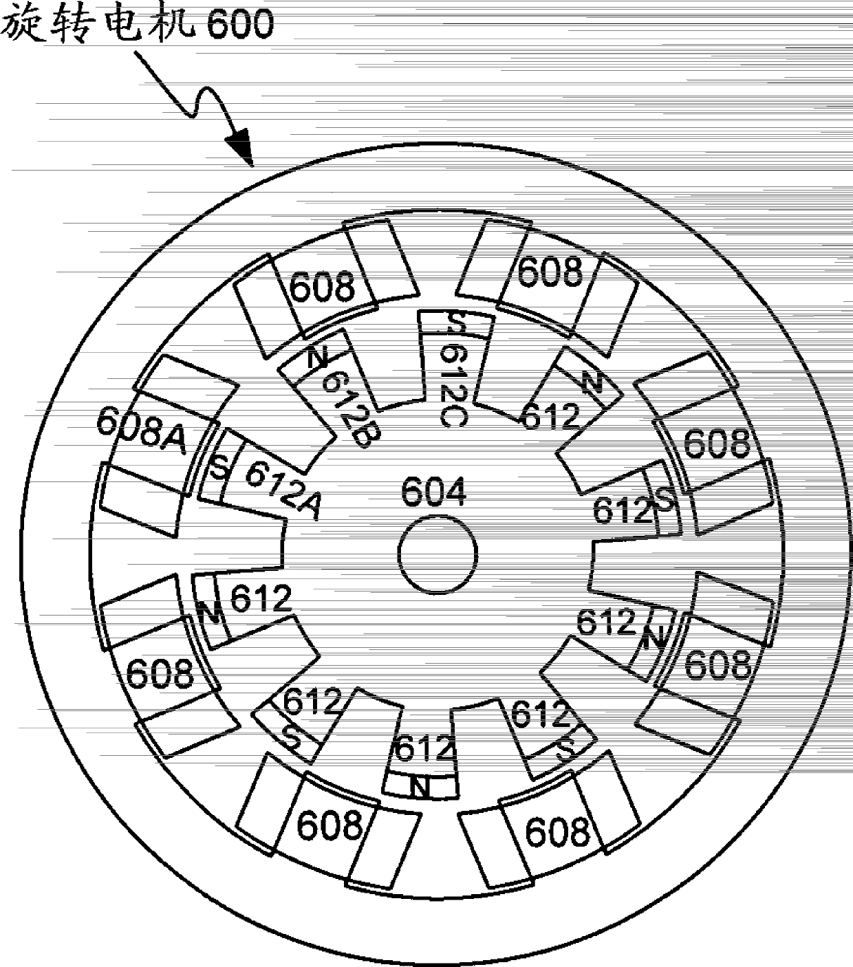
[0052] Described herein are electric machines (such as rotary motors, rotary generators, linear motors or linear generators) having two components arranged to convert between electrical energy and mechanical energy through magnetic interaction. The two components are, for example, a stator and a rotor (in a rotary electric machine) or a stator and a mover (in a linear electric machine). Each part consists of an integer number of sections of equal length (angular for rotary motors, or linear for linear motors).

[0053] motor configuration

[0054] Such as figure 1 As shown, portions such as first portion 102 and second portion 104 each include a body 106 , 108 and one or more magnetic poles 110 , 112 . In operation, the two parts 102 , 104 move relative to each other in a direction of motion 114 aligned with the aligned poles 110 , 112 . The two parts 102 , 104 interact magnetically due to the magnetic fields generated by the magnets included in the poles 110 , 112 . The...


PUM


Abstract

An electrical machine comprising: a first part, being a stator or a rotor / mover, comprising a first part having a first number of mutually spaced poles; a second part, being a rotor / mover or a stator, comprising a second part A second portion of mutually spaced apart magnetic poles, the magnetic poles of the second portion being arranged to convert between electrical energy and mechanical energy by magnetic interaction with the magnetic poles of the first portion, the second portion having substantially the same length as the first portion ; and permanent magnets in the poles of the first part or the second part, wherein the second number differs from the first number by 1 to substantially reduce the magnetic interference force in the direction of motion, wherein the gap between the poles of each part The gap depth is sufficiently deep to substantially attenuate the magnetic interaction between the body of each part and the magnetic pole of the other part, thereby reducing the magnetic interference force between the first part and the second part, and wherein each part is in Symmetrical in a direction transverse to the direction of motion between the first part and the second part and transverse to the depth of the parts to substantially balance the magnetic forces acting perpendicular to the direction of motion.

Description

technical field [0001] The present invention relates to electrical machines, in particular to electrical machines having permanent magnets arranged to reduce magnetic interference forces. Background technique [0002] In existing electrical machines, including those with permanent magnets, magnetic interference forces cause undesired energy loss, motor wear and / or disruption of smooth operation. Electric machines, also known as generators, include linear motors, rotary motors, and generators. Magnetic disturbance forces (including moments) include forces caused by magnetic interactions that prevent or at least do not facilitate efficient conversion between electrical and mechanical energy, thus reducing the efficiency and / or smooth operation of the motor. Magnetic disturbance forces can include forces against motion (such as cogging moments in rotating electric machines) and attractive forces between moving parts (such as between a rotor and a stator), which can generate fr...

Claims


Application Information

Patent Timeline
Patent Type & Authority Patents(China)
IPC IPC(8): H02K1/06
CPCH02P6/006H02K21/16H02P6/20H02P9/009H02K41/031H02K41/03H02K1/146
Inventor 钱蒂·森格钱
Owner 钱蒂 森格钱
Learn More