
Conveying device

A technology of conveying device and supply roller, which is applied in the direction of transportation and packaging, object separation, pile separation, etc., and can solve the problems of clutch device and drive side gear engagement, etc.

Active Publication Date: 2014-08-13
SEIKO EPSON CORP
View PDF5 Cites 0 Cited by
  • Summary
  • Abstract
  • Description
  • Claims
  • Application Information

AI Technical Summary

Problems solved by technology

As a result, the clutch device may engage with the drive side gear as the clutch device rotates.

Method used


Image

  • Conveying device
  • Conveying device
  • Conveying device

Examples


Embodiment Construction

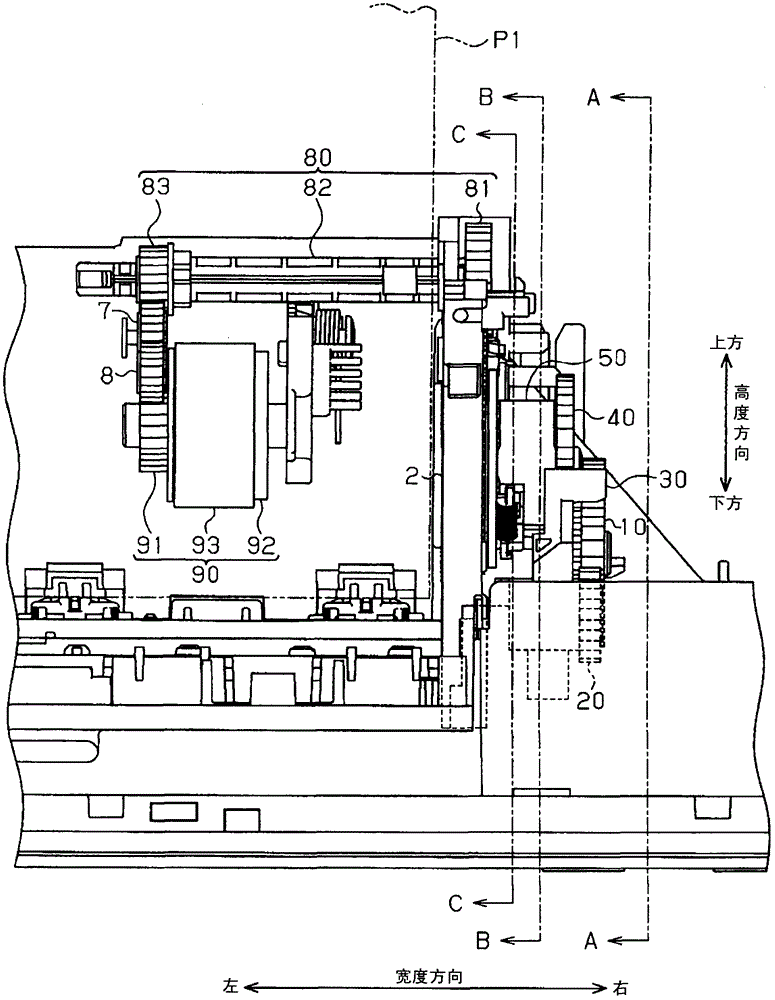
[0032] Below, use Figure 1 to Figure 12 An embodiment in which the transport device of the present invention is mounted on an inkjet printer will be described. In addition, in the following description, directions and orientations indicated by arrows in the drawings are used unless otherwise specified.

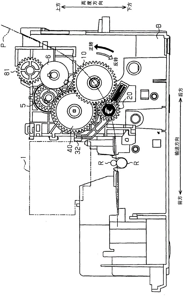
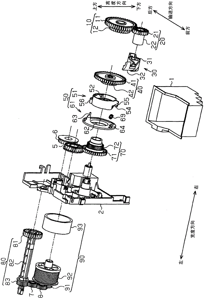
[0033] figure 1It is an enlarged front view of main parts of the conveying device mounted on the printer viewed from the front of the printer. For convenience of description, the housing of the printer and the like that are not directly related to the conveying device are omitted. in addition, figure 2 yes figure 1 A-A cutaway view. The positional relationship seen from the side of the members constituting the conveying device is clearly shown. In addition, in image 3 The shown exploded perspective view clearly shows the shape of each structural component.

[0034] Such as Figure 1 ~ Figure 3 As shown, the main part of the conveying device is rotatably supported o...


PUM


Abstract

The present invention provides a conveying device, wherein the condition that the rotation of a supply roller is transmitted from a driven gear to a driving gear is reliably suppressed. The conveying device comprises a driven gear and a driving gear, a clutch arranged between the driven gear and the driving gear for switching a transmission state into a non-transmission state. Under the transmission state, the power is transmitted from a driving source to a supply roller. Under the non-transmission state, the power is not transmitted from the driving source to the supply roller. The clutch comprises a driving detent paw (52) clamped with a driving gear, a driven detent paw (53) clamped with a driven gear and a clutch body (51) served as a single component. When the clutch body is at a non-clamping position, the clutch is maintained to be under the non-transmission state by releasing the clamping of the driving detent paw (52) and the driven detent paw (53).

Description

technical field [0001] The present invention relates to a conveying device that has a clutch that is provided between a driving side gear and a driven side gear, and that controls whether the driving force is transmitted from the driving source to the supply roller or not from the driving source to the supply roller. Switches between the non-transmission state of the roller transmission driving force. Background technique [0002] Typically, a printing device has a conveying device for conveying paper. In addition, the conveying device for conveying the cut paper adopts a structure in which the recording paper can be pulled out and loaded as needed. Here, the driving force of the driving source is transmitted to the supply roller through the driving side gear and the driven side gear that mesh with each other. Therefore, when the user draws out the paper supplied to the supply port, when the supply roller reverses, the rotation is transmitted to the drive source via the dr...

Claims


Application Information

Patent Timeline
Patent Type & Authority Patents(China)
IPC IPC(8): B65H3/06
Inventor 西中间英树山田将广
Owner SEIKO EPSON CORP
Learn More