Twin wire twisting or cabling spindle

一种倍捻锭子、捻线的技术,应用在纺织品和造纸、接头装置、连续卷绕的纺纱机等方向,能够解决给纱筒子没有受保护等问题,达到通风损失降低、驱动能量降低的效果

Inactive Publication Date: 2011-10-12
ZHUOLANG INTELLIGENT MACHINERY CO LTD
View PDF12 Cites 15 Cited by
  • Summary
  • Abstract
  • Description
  • Claims
  • Application Information

AI Technical Summary

Problems solved by technology

[0009] However, in the case of the two-for-one twisting spindle according to DE-OS 1 813 801, the yarn supply bobbin is not arranged protected in a fixed protective housing, but is placed openly on a component of the two-for-one twisting spindle in the form of a bobbin carrier

Method used


Image

  • Twin wire twisting or cabling spindle
  • Twin wire twisting or cabling spindle
  • Twin wire twisting or cabling spindle

Examples


Embodiment Construction

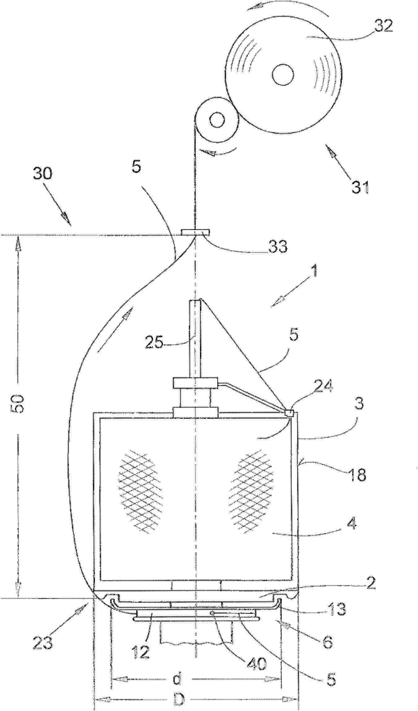
[0031] figure 1 The working position 30 of a two-for-one twister or multi-strand twister (not shown in detail) is schematically shown.

[0032]Such a working station 30 has, inter alia, a two-for-one-twisting spindle or twisting spindle 1 with a yarn supply bobbin 4 supported in a stationary protective housing 3 and for winding the twisted yarn 5 onto a winding bobbin 32 winding device 31.

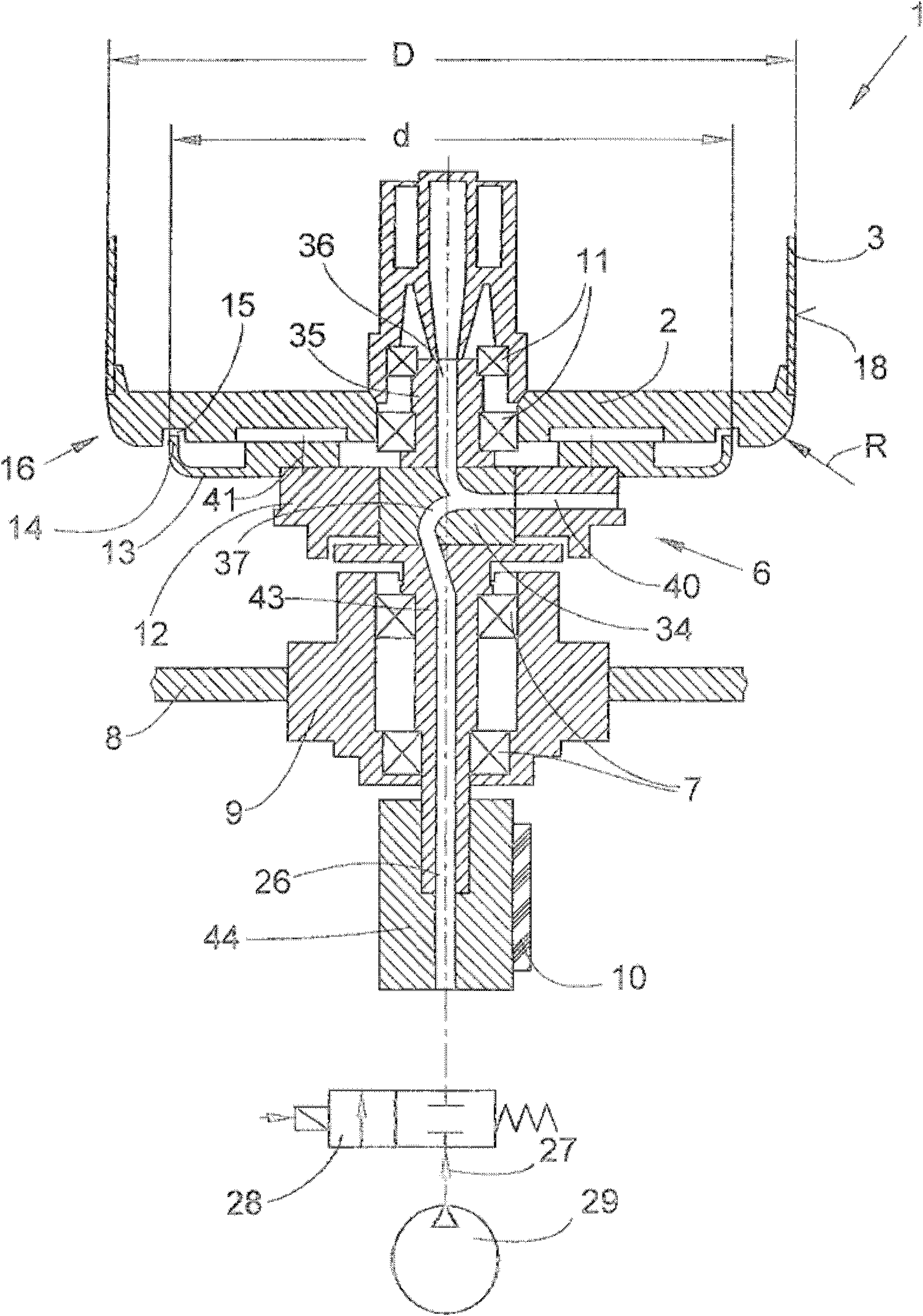
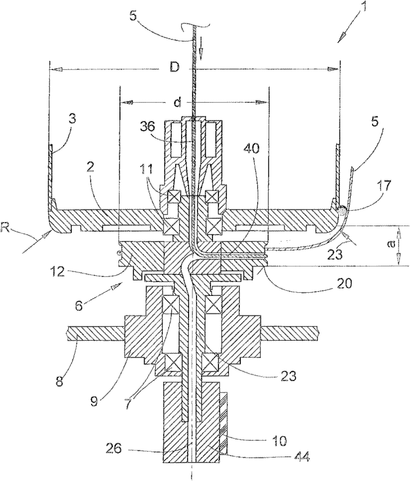
[0033] The stationary protective housing 3 with a relatively large diameter D has a housing base 2 . A rotatably mounted spindle 6 of the two-for-one twisting spindle or the twisting spindle 1 is arranged below the hood base 2 .

[0034] exist figure 1 In the illustrated embodiment, the spindle 6 is equipped with a storage disk 12 and a yarn discharge disk 13 in order to rotate and guide the yarn 5 during twisting or twisting, as shown in the figure, which constitutes a rotatable support at this time. The largest diameter of the unloading disc 13 of the spindle 6 is significantly small...


PUM


Abstract

A two-for-one twisting or cabling spindle apparatus (1) with a supply bobbin (4) mounted on a pot base (2) of a stationary protective pot (3) and a spindle (6) arranged below the protective pot (3) to guide a yarn (5) to be processed during a twisting or cabling process. The spindle (6) is rotatably mounted by a lower bearing device (7) in a bearing housing (9) fixed on a spindle rail (8) and an upper bearing device (11) mounted to the stationary protective pot (3). The largest diameter (d) of the rotatably mounted spindle (6) is at least 10% less than the diameter (D) of a touching line (23) of the pot base (2) of the stationary protective pot (3) with the yarn (5).

Description

technical field [0001] The invention relates to a two-for-one twist spindle or a twist spindle according to the preamble of claim 1 . Background technique [0002] A modern two-for-one twisting spindle or twisting spindle usually has a stationary protective housing for housing the yarn supply bobbin, a hollow bobbin shaft to guide the yarn through the twisting spindle, and a rotatably supported rotatable Driven spindle. That is to say, in such two-for-one twisting spindles or twisting spindles, the yarn is drawn upwards from the stationary yarn supply bobbin, is fed into the upper end of the hollow bobbin shaft and is simultaneously turned downwards. In the bobbin, the yarn is guided past the yarn brake and then out of the bobbin shaft region through a radial hole which is provided in a component of the rotatably mounted and drivable spindle. After coming out of the radial hole, the yarn is temporarily stored on the yarn storage disc of the spindle, and then the yarn is se...

Claims


Application Information

Patent Timeline
Patent Type & Authority Applications(China)
IPC IPC(8): D01H7/86D01H7/88D01H13/10
CPCD01H1/106D01H7/868D01H15/007
Inventor 马库斯·贝克曼乔治·海嫩沃尔夫冈·洛伊佩斯格尔德·波勒曼于尔根·施尼茨勒迪特尔·斯塔赫伦乔治·特茨拉夫
Owner ZHUOLANG INTELLIGENT MACHINERY CO LTD
Why Eureka
Try Eureka