Performance apparatus

a technology of performance apparatus and performance device, which is applied in the direction of electrophonic musical instruments, automatic musical instruments, instruments, etc., can solve the problems of high power consumption, waste of energy, and above-proposed performance apparatuses, and achieve the effect of reducing energy consumption

Inactive Publication Date: 2006-04-25
YAMAHA CORP
View PDF3 Cites 5 Cited by
  • Summary
  • Abstract
  • Description
  • Claims
  • Application Information

AI Technical Summary

Benefits of technology

[0010]It is a first object of the present invention to provide a performance apparatus that can reduce energy consumption while allowing sounding elements to properly generate sound.

Problems solved by technology

However, the above proposed performance apparatuses have problems described below.
Consequently, high power is consumed even in a range of the operating stroke in which large energy is not needed, and energy is thus wasted.
Another problem with the proposed performance apparatuses is that more driving energy than required is applied to the sounding element acting member such as the rotating member and the actuator so that the sounding element acting member and the actuator strongly engage or urgingly contact each other, to generate a loud mechanical noise.
Further, if it is configured such that a reciprocating member such as the plunger comes into contact with a stopper to define the end of the operating stroke of the reciprocating member, then a mechanical noise which is not negligible is generated due to the urging contact between the reciprocating member and the stopper.

Method used


Image

  • Performance apparatus
  • Performance apparatus
  • Performance apparatus

Examples


first embodiment

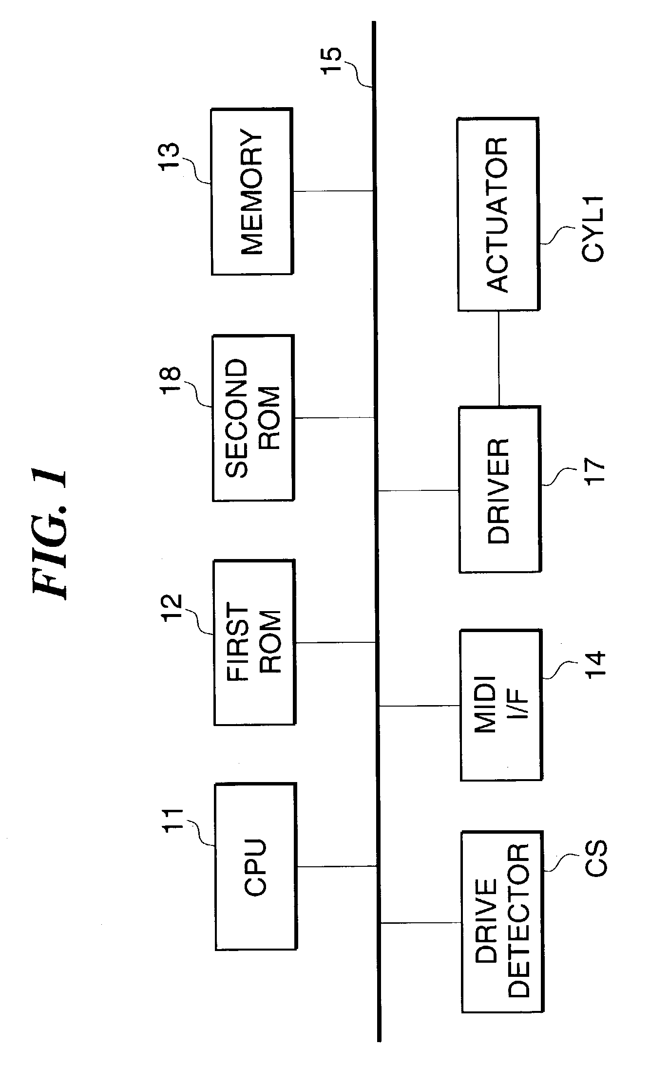
[0046]FIG. 1 is a block diagram showing the construction of a control section of a performance apparatus according to the present invention.

[0047]The performance apparatus according to the present embodiment is comprised of a first ROM 12, a memory 13 (storage device), a MIDI interface (MIDI I / F) 14, a second ROM 18, and drive detectors CS (operative state detecting device), a driver 17, and a CPU 11 to which the above component parts are connected via a bus 15. The CPU 11 controls the entire apparatus. The first ROM 12 is comprised of a program ROM, a data ROM, and a working ROM, none of which are shown, and stores control programs to be executed by the CPU 11, various data, and so on. The MIDI I / F 14 receives performance data input from a MIDI instrument, not shown, or the like, as MIDI (Musical Instrument Digital Interface) signals. The memory 13 is comprised of a RAM or the like, and stores various data including performance data and can store performance data input from the MID...

second embodiment

[0092]Now, the present invention will be described with reference to FIGS. 1, 5, and 7 to 9.

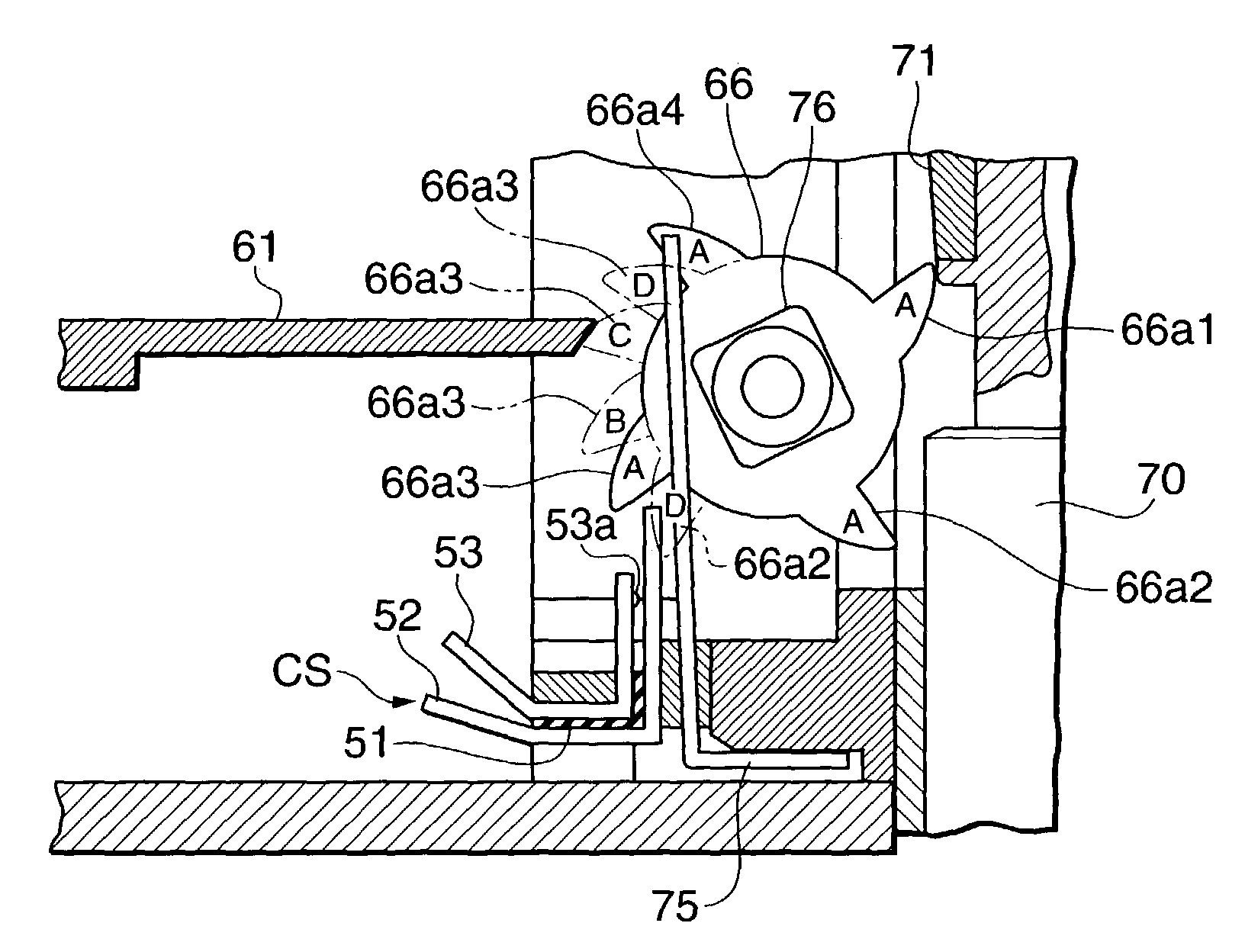
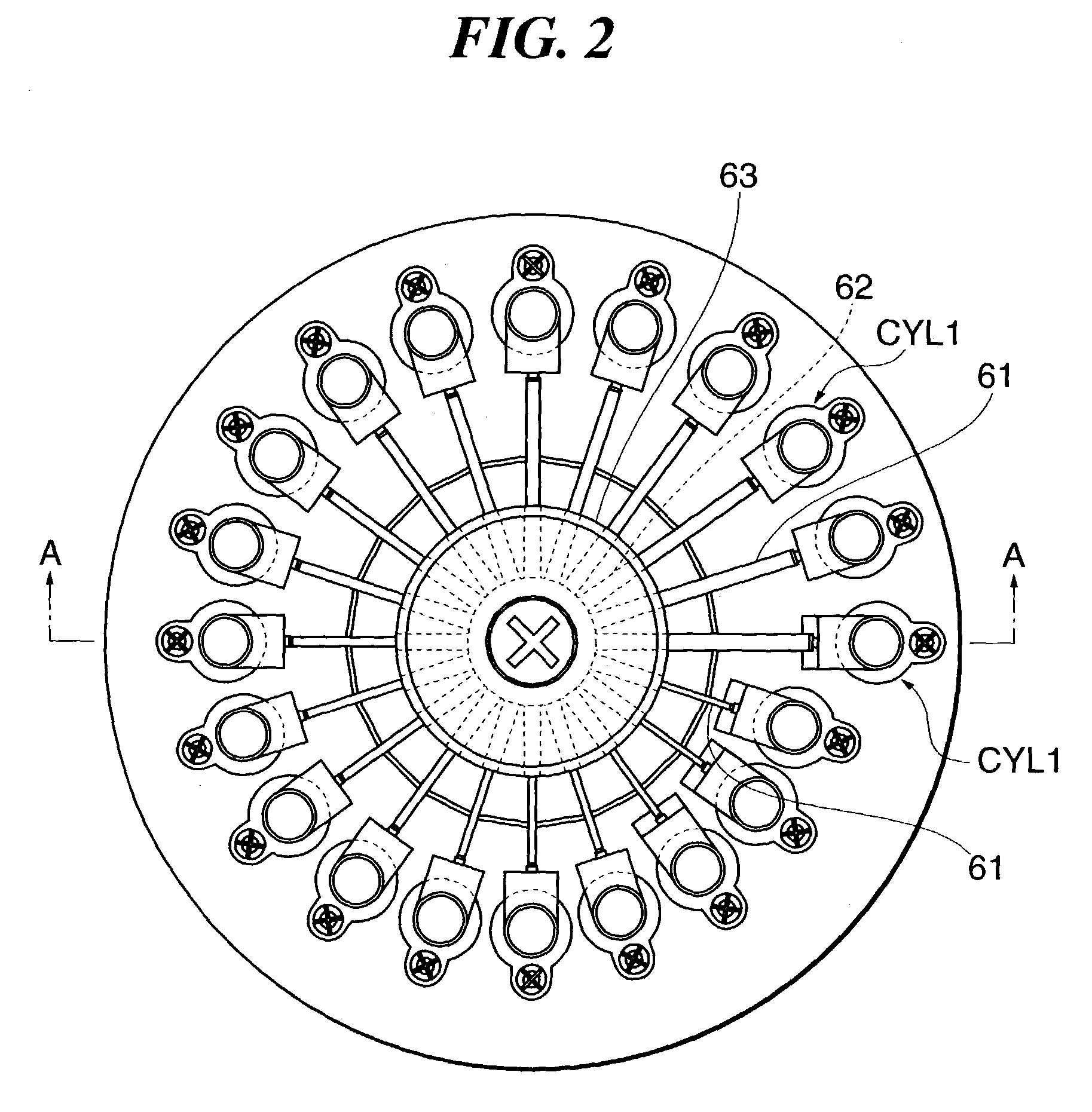
[0093]FIG. 8 is a top plan view of a performance apparatus according to the second embodiment of the present invention. FIG. 9A is a sectional view of this apparatus. FIG. 9B is a front view showing essential parts of the apparatus as viewed from a left side in FIG. 9A. FIG. 9C is an enlarged fragmentary view of a channel-shaped stepped space and a driving nail of a rotary pick.

[0094]In the second embodiment, the construction of the control section is basically the same as that shown in FIG. 1 in the first embodiment. However, an actuator FLAT2, which is implemented by a flat coil type, is employed in place of the actuator CYL1. Further, a drive detector CS2 is employed in place of the drive detector CS. The actuator FLAT2 is drivingly controlled by pulse width modulation (PWM) as is the case with the first embodiment (see FIG. 7). The PWM table is also updated as is the case with the first e...


PUM


Abstract

There is provided a performance apparatus that can reduce energy consumption while allowing sounding elements to appropriately generate sound. A CPU supplies driving energy to an actuator to drivingly control the same based on pulse width modulation. A rotary pick is rotatively driven by the actuator to pluck reeds to generate sound. The CPU sets the duty of a driving pulse for driving the rotary pick during time points t3 and t4. Thus, higher driving energy is supplied to the actuator in timing in which the rotary pick plucks any of the reeds than in timing in which the rotary pick does not pluck any of the reeds.

Description

BACKGROUND OF THE INVENTION[0001]1. Field of the Invention[0002]The present invention relates to a performance apparatus that applies driving energy such as electricity to a sounding element acting member to cause sounding elements such as reeds to generate sound.[0003]2. Description of the Related Art[0004]A performance apparatus such as a music box type has hitherto been known which causes sounding elements such as reeds to generate sound by means of a driving device such as a solenoid coil, that acts upon or plucks the sounding elements, without using a barrel drum.[0005]For example, a performance apparatus of this type has been proposed by the assignee of the present application (Japanese Patent Application No. 2002-079132). This performance apparatus is comprised of a rotating member acting as a sounding element acting member and provided with a plurality of driving nails in its outer periphery, and a swing arm with a flat coil, acting as an actuator. The flat coil is disposed ...

Claims


Application Information

Patent Timeline
Patent Type & Authority Patents(United States)
IPC IPC(8): G10F1/06
CPCG10F1/06
Inventor KANEKO, YASUTOSHIMURAMATSU, SHIGERU
Owner YAMAHA CORP
Why Eureka
Try Eureka