Automatic three-dimensional radio frequency identification (RFID) test device

A test device and three-dimensional technology, applied in the field of radio frequency identification, can solve the problems of no automated test method and inability to perform automated continuous testing, and achieve the effect of improving test efficiency and accuracy and improving test efficiency.

Inactive Publication Date: 2011-10-12
叶永嘉
View PDF0 Cites 15 Cited by
  • Summary
  • Abstract
  • Description
  • Claims
  • Application Information

AI Technical Summary

Problems solved by technology

[0007] But these methods and equipment do not provide a kind of automated testing means
Especially when the electronic

Method used


Image

  • Automatic three-dimensional radio frequency identification (RFID) test device
  • Automatic three-dimensional radio frequency identification (RFID) test device
  • Automatic three-dimensional radio frequency identification (RFID) test device

Examples


Embodiment Construction

[0037] In order to better illustrate the purpose and advantages of the present invention, the present invention will be further described in detail below in conjunction with the accompanying drawings and embodiments:

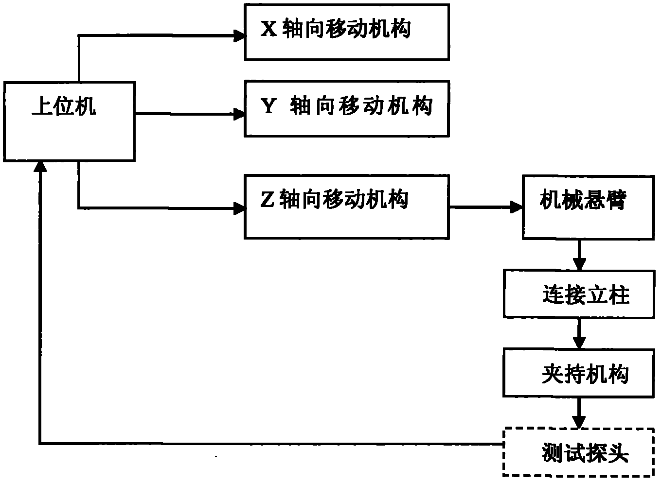
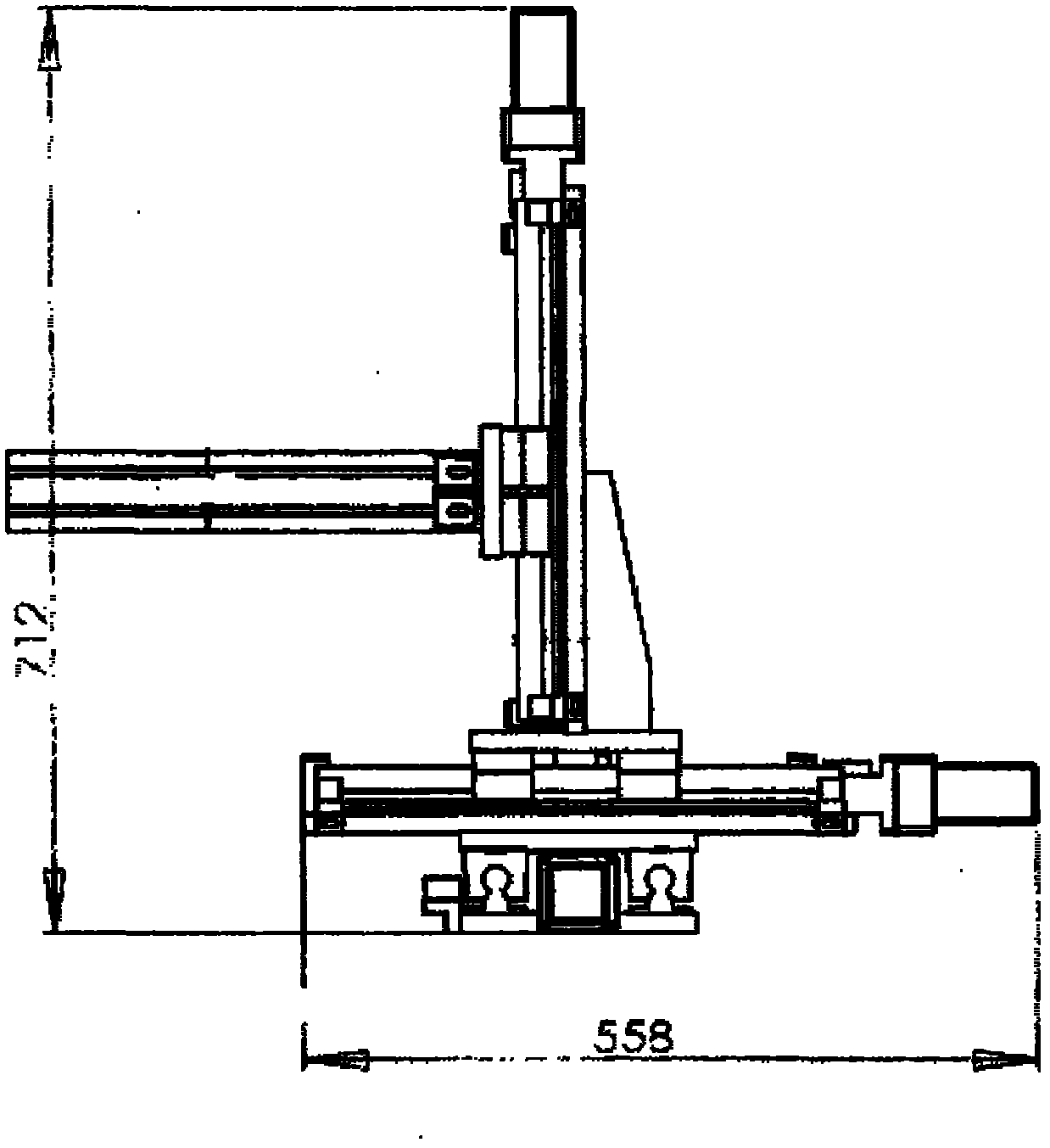
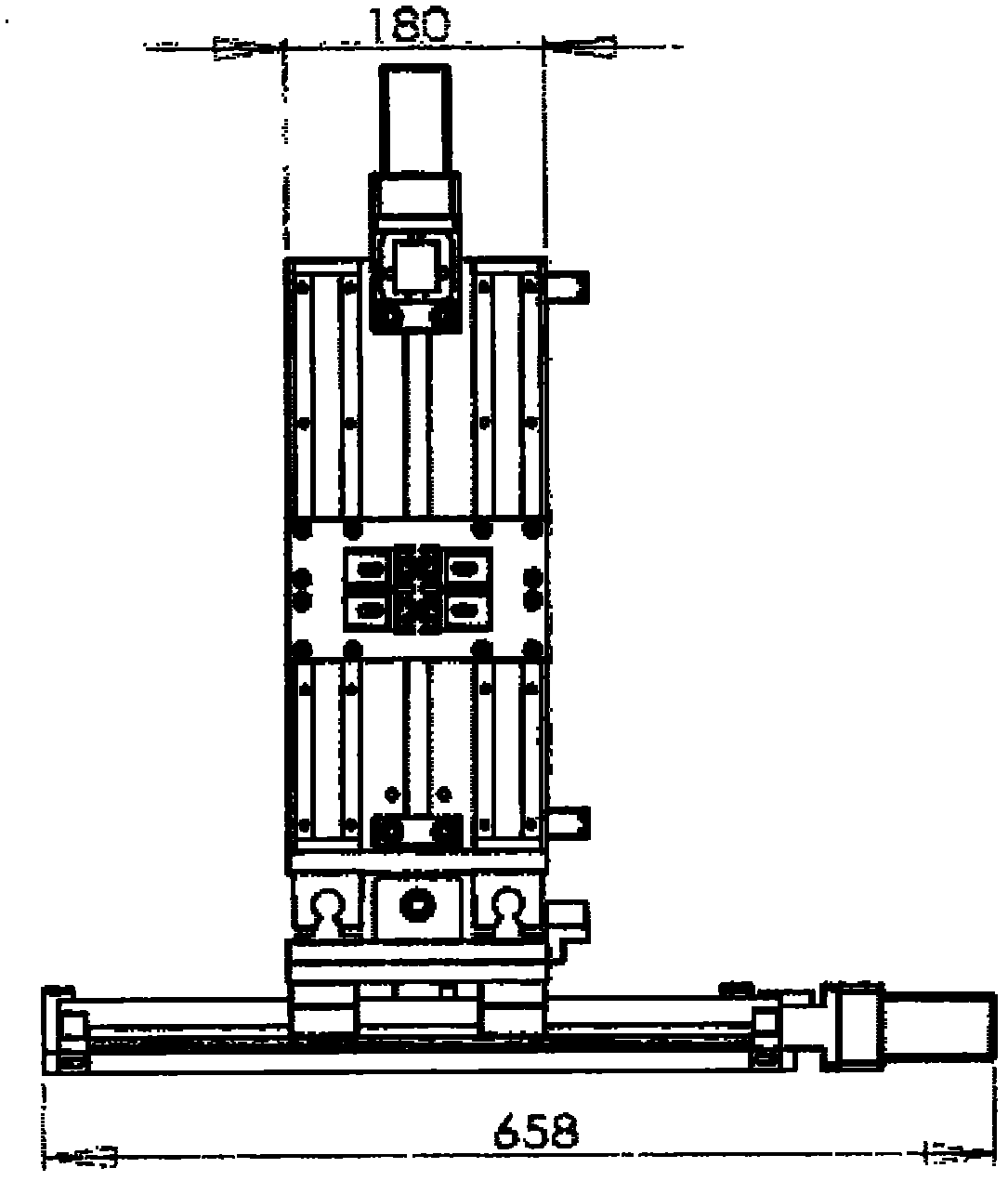
[0038] The three-dimensional automatic RFID testing device of the present invention comprises host computer, connecting column 15, clamping mechanism (comprising plastic box body 12, sliding sheet 13, test probe 14), mechanical cantilever 11 and three-dimensional moving mechanism 1; Wherein three-dimensional moving mechanism 1 comprises An X-axis moving mechanism 8 , a Y-axis moving mechanism 9 and a Z-axis moving mechanism 10 . like Figure 5 , Image 6 and Figure 7 shown.

[0039] The structure of the moving mechanism in each direction is the same, including a lead screw, a stepping motor and two limit switches, such as Figure 4 shown. For the X-axis moving mechanism, the X-axis stepping motor 2 is installed on one end of the X-axis screw 5; the X-axis ...


PUM


Abstract

The invention relates to an automatic three-dimensional radio frequency identification (RFID) test device, and belongs to the technical field of RFID. The device comprises an upper computer, a three-dimensional moving mechanism, a mechanical cantilever, a connecting vertical post and a clamping mechanism, wherein the three-dimensional moving mechanism mainly comprises an X-axis moving mechanism, a Y-axis moving mechanism and a Z-axis moving mechanism which are assembled into a whole respectively according to an X-axis direction, a Y-axis direction and a Z-axis direction; one end of the mechanical cantilever is vertically installed on the Z-axis moving mechanism and the other end of the mechanical cantilever is vertically installed with the connecting vertical post; the clamping mechanism is arranged below the connecting vertical post; and the lower surface of the clamping mechanism is opposite to a test RFID reader. The device is designed based on an RFID reader antenna and a mobile phone terminal integrated with an electronic tag, the field intensity distribution of any one horizontal plane above the reader can be automatically tested, and the space distribution and a signal wave form of an electromagnetic field can be intuitively understood so as to analyze the performance of the reader, determine the maximum test distance and test the direction sensitivity.

Description

technical field [0001] The invention relates to a three-dimensional automatic RFID testing device, which belongs to the technical field of radio frequency identification. Background technique [0002] Radio Frequency Identification (Radio Frequency Identification, abbreviated as RFID) is an automatic identification technology that began to emerge in the 1990s. Radio Frequency Identification technology is a technology that uses radio frequency signals to achieve non-contact information transmission and A technology that achieves the purpose of identification through the transmitted information. [0003] From the basic principle of information transmission, radio frequency identification technology is based on the transformer coupling model (energy transfer and signal transmission between primary and secondary) in the low frequency band, and based on the spatial coupling model of radar detection targets in the high frequency band (radar emits electromagnetic wave signals Afte...

Claims


Application Information

Patent Timeline
IPC IPC(8): G01R33/10G01R29/14
Inventor 叶永嘉
Owner 叶永嘉
Why Eureka
Try Eureka