
Direct-current solid-state circuit breaker

A DC power supply, thyristor technology, applied in the protection, electrical components, electronic switches and other directions that react to overcurrent, can solve the problems of unreliable shutdown, leakage, power supply shock, etc., to avoid the voltage drop of the energy storage pulse capacitor Effect

Inactive Publication Date: 2014-04-09
NANJING UNIV OF AERONAUTICS & ASTRONAUTICS
View PDF3 Cites 0 Cited by
  • Summary
  • Abstract
  • Description
  • Claims
  • Application Information

AI Technical Summary

Problems solved by technology

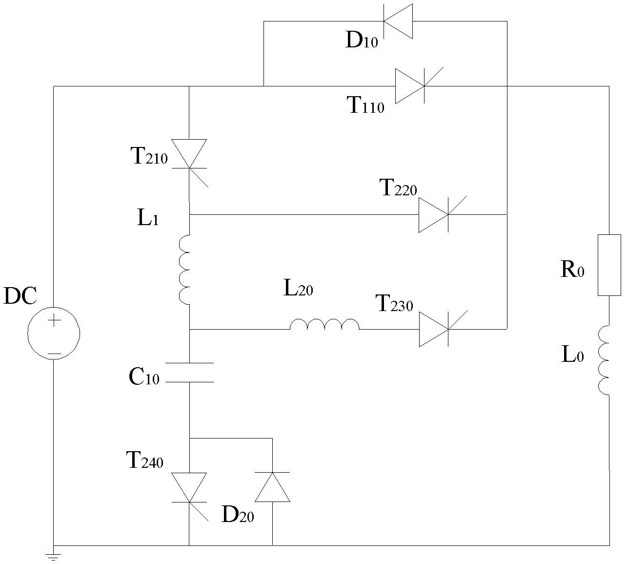
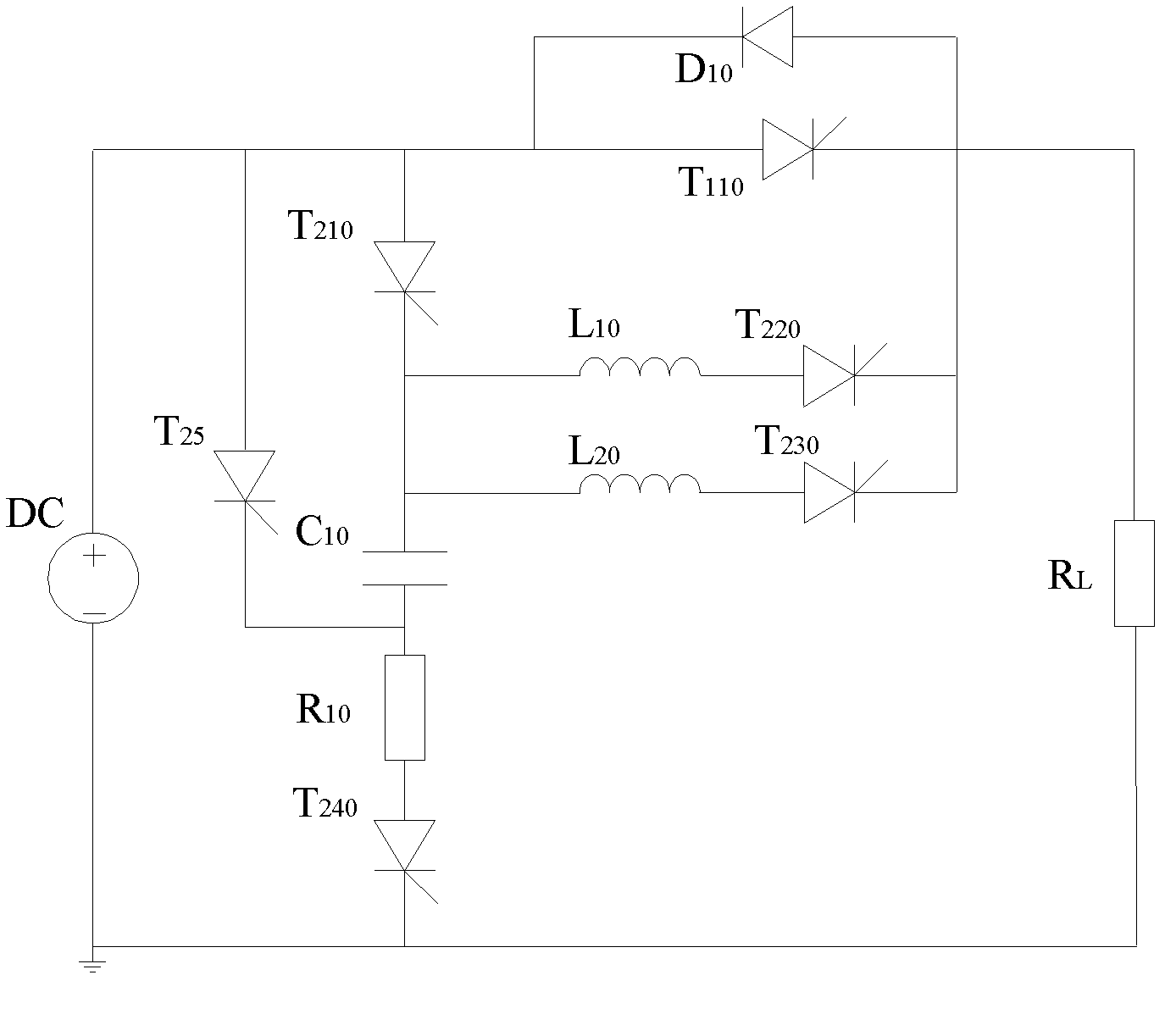
The key to its normal shutdown is the energy storage pulse capacitor C 10 with inductance L 10 LC resonance occurs and the resonance current is greater than the operating current of the load. In this structure, the energy storage pulse capacitor C 10 with inductance L 10 The necessary condition for LC resonance to occur is the energy storage pulse capacitor C 10 The voltage is higher than the power supply voltage, and due to the existence of the leakage resistance of the thyristor and the leakage resistance of the capacitor, it is bound to cause the energy storage pulse capacitance C 10 The energy through the thyristor T 220 and T 230 leakage to the load, when the energy storage pulse capacitor C 10 When the voltage drops to the power supply voltage due to energy leakage, the energy storage pulse capacitor C 10 with inductance L 10 Failure to reach the necessary conditions for resonance will eventually cause the shutdown failure of the SSCB; for this defect, an improved topology such as figure 2 , this topology uses the power supply voltage to reduce the impact on the energy storage pulse capacitor C when the LC resonance occurs 10 Although the voltage requirement effectively solves the problem of unreliable shut-off caused by the inherent leakage current of the device, when the short-circuit fault shuts down, because the resonant circuit contains the power supply, the power supply will flow a large resonant current. Great impact on the power supply

Method used


Image

  • Direct-current solid-state circuit breaker
  • Direct-current solid-state circuit breaker
  • Direct-current solid-state circuit breaker

Examples


Embodiment Construction

[0019] The technical solutions of the present invention will be described in detail below in conjunction with the accompanying drawings.

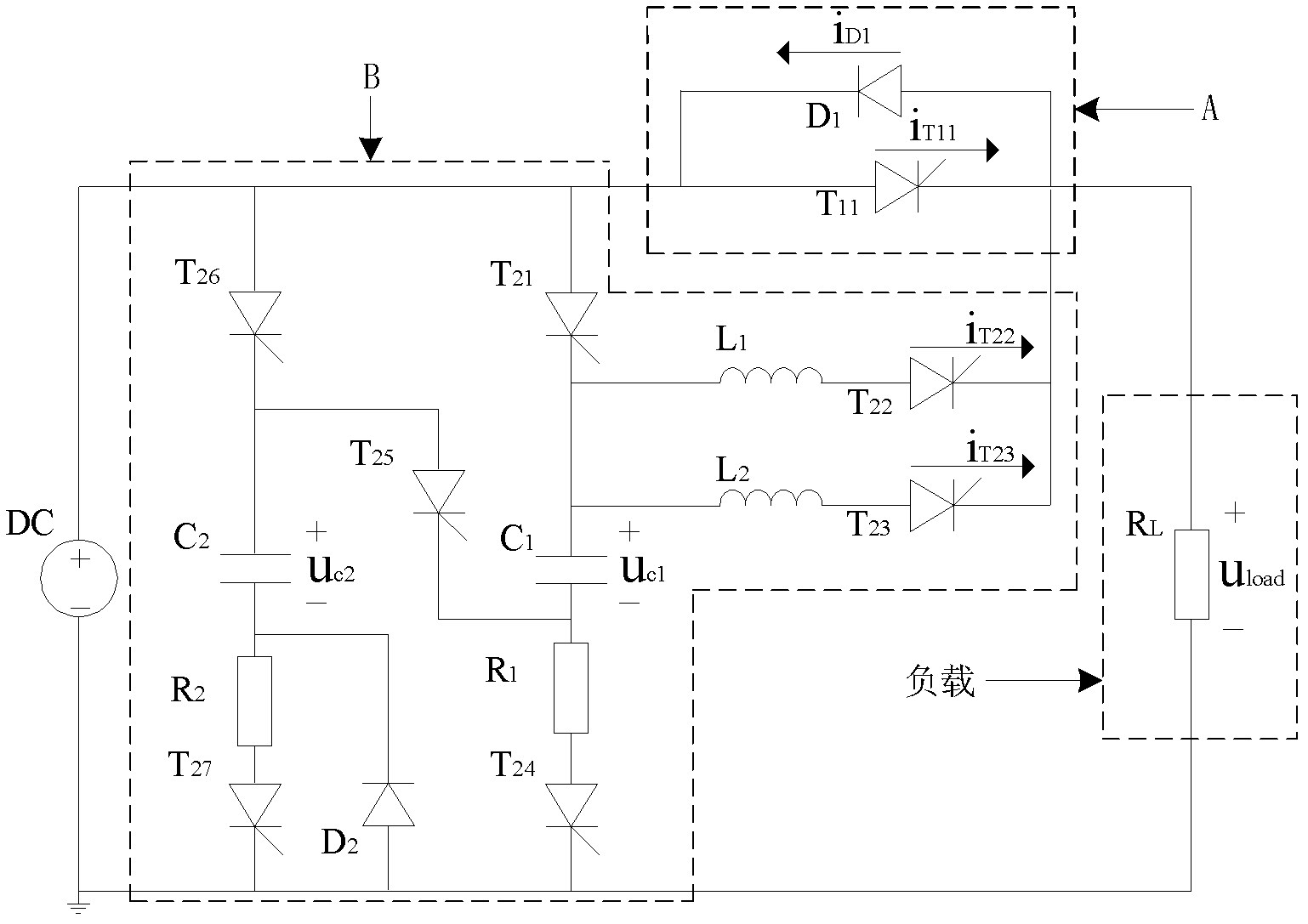
[0020] The invention provides a DC solid-state circuit breaker, the circuit of which is as follows image 3 Shown, where A is the main switch unit, B is the auxiliary switch unit. Among them, the main switch unit A includes: the main switch thyristor T 11 and the main switching power diode D 1 ; The auxiliary switch unit B mainly includes the first thyristor T 21 , the second thyristor T 22 , the third thyristor T 23 , the fourth thyristor T 24 , the fifth thyristor T 25 , the sixth thyristor T 26 , the seventh thyristor T 27 , the first inductance L 1 , the second inductance L 2 , the first energy storage pulse capacitor C 1 , the second energy storage pulse capacitor C 2 , the first current limiting power resistor R 1 , the second current limiting power resistor R 2 and freewheeling diode D 2 .

[0021] Among them, the aux...


PUM


Abstract

The invention discloses a direct-current solid-state circuit breaker which comprises a direct current power supply and a load, and also comprises a master switch unit A and an auxiliary switch unit B, wherein the master switch unit A comprises a master switch thyristor and a master switch power diode, and the auxiliary switch unit B comprises a first thyristor, a second thyristor, a third thyristor, a fourth thyristor, a fifth thyristor, a sixth thyristor, a seventh thyristor, a first inductance, a second inductance, a first storage pulse capacitor, a second storage pulse capacitor, a first current-limiting power resistor, a second current-limiting power resistor and a fly-wheel diode. The structure in the invention can effectively avoid the problems that the inherent leakage current of the devices can lower the voltage of the storage pulse capacitor, and large resonance currents can flow through the power supply when the power supply is unreliably or faultily turned off.

Description

technical field [0001] The invention belongs to the technical field of power electronics and electric engineering, and in particular relates to a circuit structure of a DC solid-state circuit breaker. Background technique [0002] Solid State Circuit Breaker (SSCB for short) is a new type of power automation equipment used to quickly cut off faults, because of its short switching time, no sound, no arc, no dead zone, long life and working reliability High advantages, has great application prospects. At present, AC solid-state circuit breakers are used more. In the field of DC, there are also studies on thyristor-based DC solid-state circuit breakers, such as a vibration-type DC solid-state circuit breaker provided by a Chinese invention patent (patent number: 200910026473.8), see figure 1 . The key to its normal shutdown is the energy storage pulse capacitor C 10 with inductance L 10 LC resonance occurs and the resonance current is greater than the operating current of ...

Claims


Application Information

Patent Timeline
Patent Type & Authority Patents(China)
IPC IPC(8): H02H3/08H03K17/72
Inventor 王莉欧世峰
Owner NANJING UNIV OF AERONAUTICS & ASTRONAUTICS
Learn More