
Economizer with condensed water guide plate

An economizer and condensate technology, applied in feed water heaters, preheating, steam generation, etc., can solve problems such as pollution, achieve the effects of prolonging service life, protecting equipment, and simple structure

Inactive Publication Date: 2014-08-13
PUYANG XINGTAI METAL STRUCTURE PROD
View PDF8 Cites 0 Cited by
  • Summary
  • Abstract
  • Description
  • Claims
  • Application Information

AI Technical Summary

Problems solved by technology

[0003] In view of the above situation, in order to overcome the defects of the prior art, the object of the present invention is to provide an economizer with a condensed water deflector, which effectively solves the problem of the flow direction of the condensed water, and does not affect equipment such as boilers or heating furnaces. Cause corrosion, condensed water will not flow to the ground, causing pollution to the environment
[0005] The invention has a simple structure, effectively solves the problem of the flow direction of the condensed water, does not cause corrosion to equipment such as boilers or heating furnaces, protects the equipment, prolongs the service life of the equipment, and prevents the condensed water from flowing to the ground and causing pollution to the environment. It will not flow to the ground to freeze in winter, preventing operators from falling

Method used


Image

  • Economizer with condensed water guide plate
  • Economizer with condensed water guide plate
  • Economizer with condensed water guide plate

Examples


Embodiment Construction

[0009] The specific implementation manners of the present invention will be described in further detail below in conjunction with the accompanying drawings.

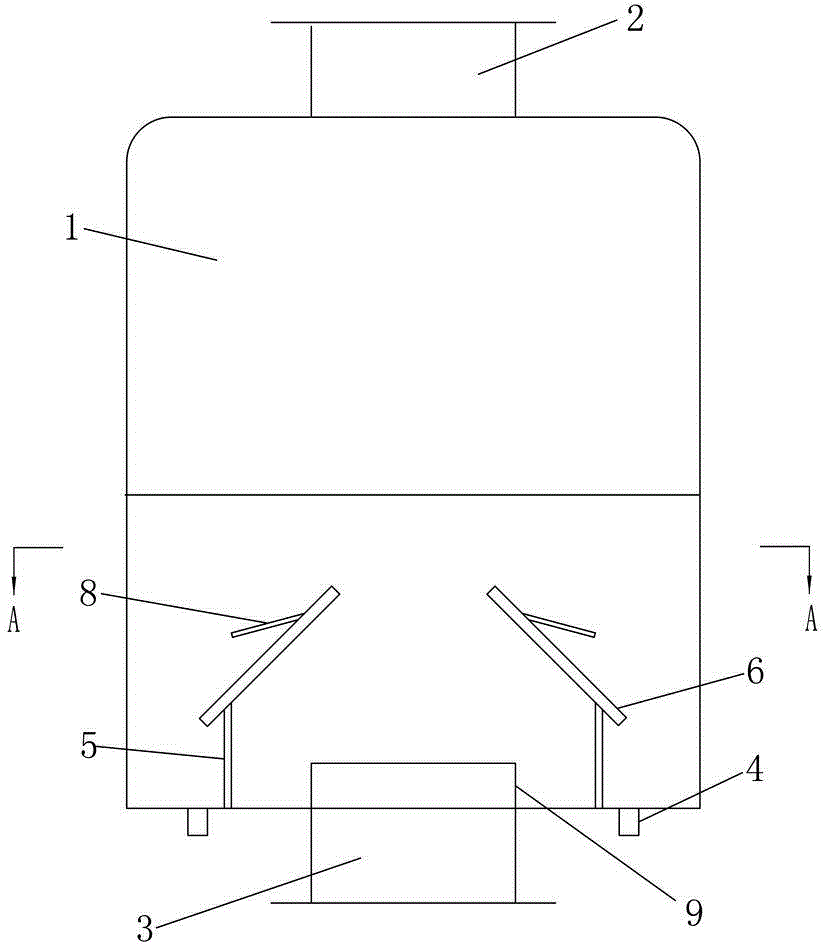
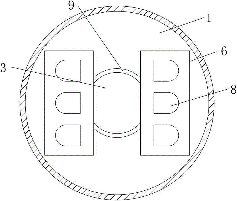
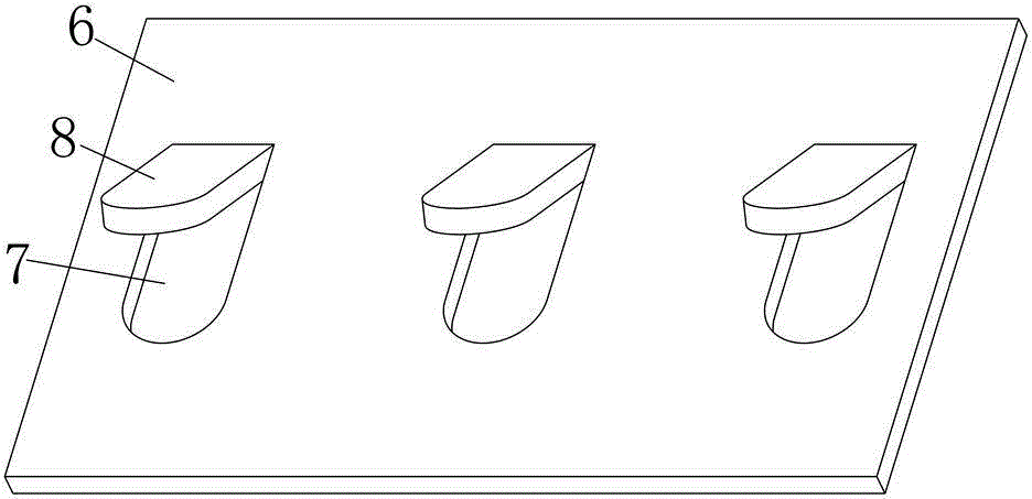
[0010] Depend on Figure 1 to Figure 3 Given, the present invention includes an economizer, the upper end of the economizer 1 has a flue gas outlet 2, the middle of the lower end has a flue gas inlet 3, and both sides of the flue gas inlet 3 have drainage ports 4, and the energy saving between the flue gas inlet 3 and the drainage port 4 There is a support rod 5 on the inner bottom plate of the device 1, the upper end of the support rod 5 is equipped with a smoke distribution plate 6, and the lower end of the smoke distribution plate 6 is inclined towards the direction of the water outlet 4, and the smoke distribution plate 6 is longitudinally spaced with multiple A flue gas distribution port 7, the upper side of the flue gas distribution port 7 is equipped with a condensed water distribution plate 8, the lower end of th...


PUM


Abstract

The invention relates to an economizer with a condensed water guide plate. The scheme is that the economizer comprises an economizer body, wherein a smoke outlet is arranged at the upper end of the economizer, a smoke inlet is arranged in the middle of the lower end, drain ports are formed in two sides of the smoke inlet, a supporting rod is arranged on an inner base plate in the economizer body between the smoke inlet and the drain ports, a smoke distributing plate is installed at the upper end of the supporting rod, the lower end of the smoke distributing plate inclines towards the direction of the drain ports, multiple smoke distributing ports are longitudinally formed in the smoke distributing plate at intervals, condensed water distributing plates are installed on the upper sides of the smoke distributing ports, the lower ends of the condensed water distributing plates upward incline relative to the smoke distributing plate, and the inner base plate in the economizer body is provided with a water blocking plate surrounding the smoke inlet. The flowing direction problem of condensed water is solved, a boiler or a heating furnace and other devices are not corroded and are protected, the service life of the devices is prolonged, the condensed water does not flow towards the ground, environment pollution is not caused, the condensed water does not flow onto the ground and ices up in winter, and operators are prevented from being injured due to falling down.

Description

technical field [0001] The invention relates to an economizer for boilers and heating furnaces specialized in storage and transportation of crude oil, in particular to an economizer with a condensed water deflector. Background technique [0002] During the combustion process of boilers and heating furnaces, since the demineralized water in the drum continuously evaporates to generate steam, it is necessary to continuously replenish demineralized water into the drum to prevent the boiler from burning dry. The demineralized water is at room temperature. For a long time, the economizer is to use the boiler or heating furnace exhaust to preheat the demineralized water ready to enter the boiler to improve thermal efficiency and save fuel. However, the normal temperature demineralized water and high temperature flue gas in the economizer During the exchange, a large amount of condensed water is generated and flows into the boiler or heating furnace, which accelerates the corrosion...

Claims


Application Information

Patent Timeline
Patent Type & Authority Applications(China)
IPC IPC(8): F22D1/02
Inventor 徐东海李东霞
Owner PUYANG XINGTAI METAL STRUCTURE PROD
Learn More