
Method and apparatus for improving water noise of LCD

A liquid crystal display and watermark technology, applied to static indicators, instruments, color TV parts, etc., to achieve the effect of improving watermark noise and picture quality

Active Publication Date: 2010-11-17
K TRONICS (SUZHOU) TECH CO LTD +1
View PDF3 Cites 0 Cited by
  • Summary
  • Abstract
  • Description
  • Claims
  • Application Information

AI Technical Summary

Problems solved by technology

[0009] The purpose of the first aspect of the present invention is to provide a method for improving the water streak noise of a liquid crystal display, which can solve the flow problem of the water streak noise, further improve the water streak noise that stops flowing, and improve the picture quality
[0010] The purpose of the second aspect of the present invention is to provide a device for improving watermark noise in liquid crystal displays, which can solve the flow problem of watermark noise, further improve watermark noise that stops flowing, and improve picture quality

Method used


Image

  • Method and apparatus for improving water noise of LCD
  • Method and apparatus for improving water noise of LCD
  • Method and apparatus for improving water noise of LCD

Examples


no. 1 example

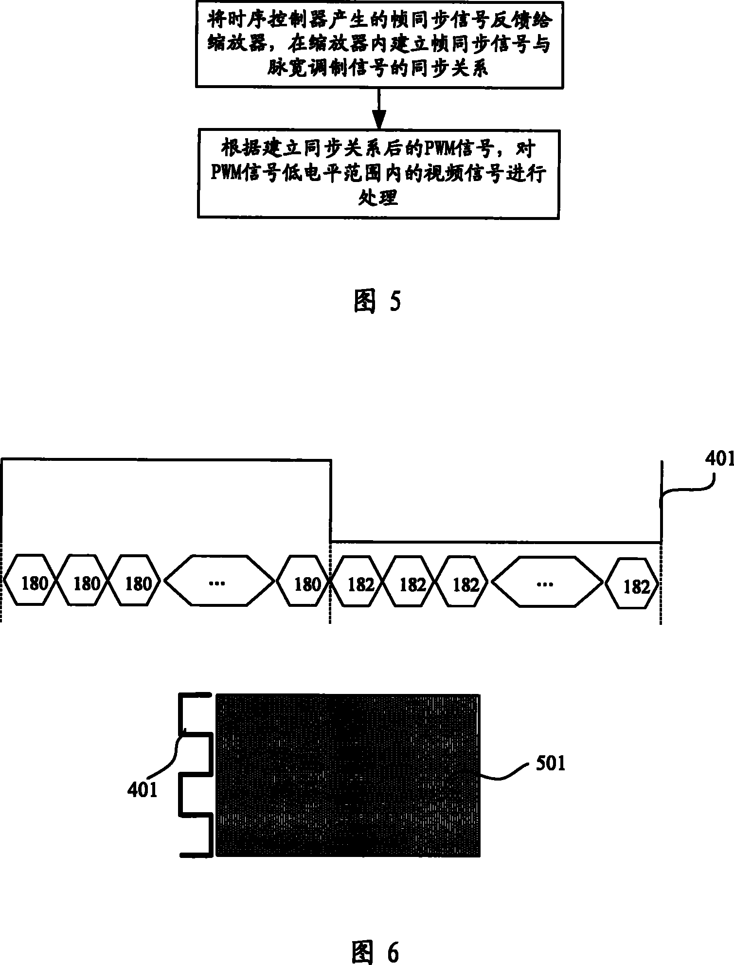
[0028] Such as Figure 5 Shown is a flow chart of the first embodiment of the first aspect of the present invention, wherein the following steps are performed:

[0029] Step 1. Feedback the frame synchronization signal generated by the timing controller to the scaler, and establish a synchronization relationship between the frame synchronization signal and the pulse width modulation signal in the scaler;

[0030] Step 2. According to the PWM signal 401 after the synchronous relationship is established, the video signal in the low level range of the PWM signal 401 is processed to reduce the brightness difference between the bright and dark areas of the video signal.

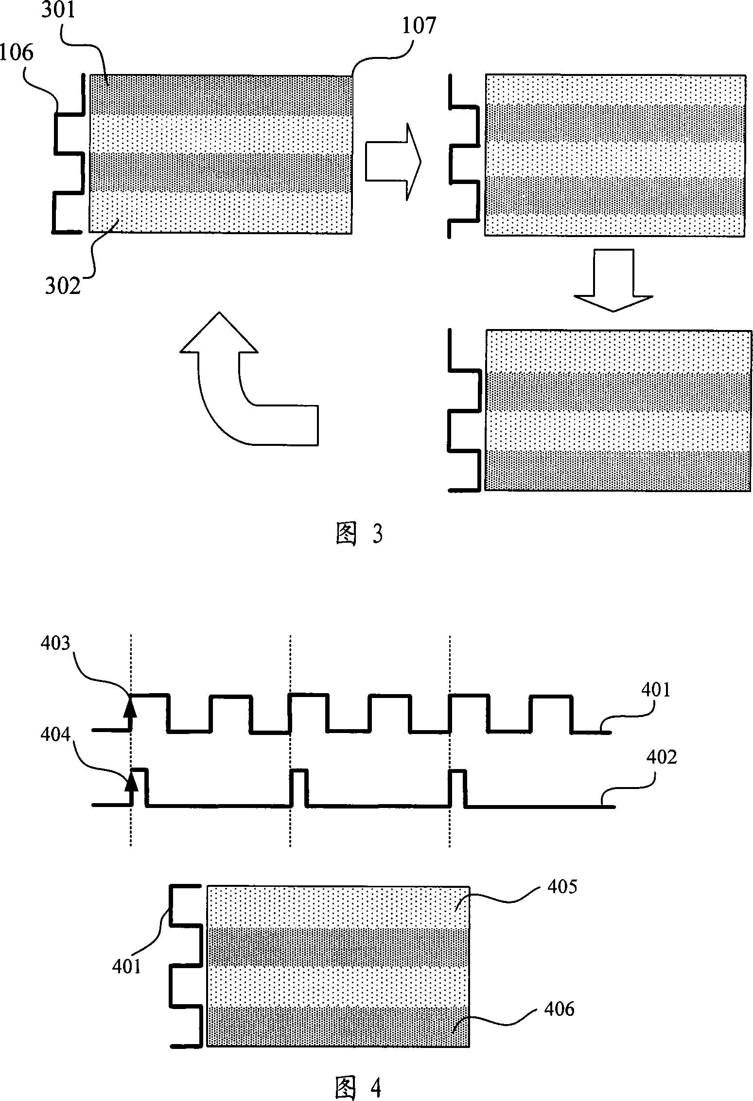
[0031] Such as Figure 4 As shown, it is a schematic diagram of the stopped water ripple noise in the first embodiment of the first aspect of the present invention, assuming that the frequency of the PWM signal 401 is F PWM =120Hz, the frequency of the frame synchronization signal 402 is F FR =60Hz, namely F P...

no. 2 example

[0037] Step 2 of the first embodiment of the first aspect of the present invention can also be: according to the PWM signal 401 after the synchronization relationship is established, the video signal in the high level range of the PWM signal 401 is processed to reduce the bright and dark areas of the video signal difference in brightness.

[0038] Such as Figure 7 As shown, it is a schematic diagram of the second embodiment of the first aspect of the present invention, the PWM signal 401 is used as the enable signal of the subtractor in the timing controller 102, the high level is active, and the video signal is input into the subtractor; when the PWM When the signal 401 is at low level, the subtractor is in a non-working state, and directly outputs the video signal; when the PWM signal 401 is at a high level, the subtractor is in a working state, and reduces the video signal by a set value.

[0039] The set value can be adjusted by the register 102 in the timing controller ...


PUM


Abstract

The invention relates to a method for improving water traces noise of a liquid crystal display device and a device, the method executes the following steps: frame synchronization signals which are produced by a time schedule controller is feedback to a scaler, a synchronous relationship of the frame synchronization signals and pulse width modulation signals is built in the scaler, video signals are treated according to the pulse width modulation signals after the synchronous relationship is built, thereby reducing the luminance difference of light and shade areas of the video signals. The device comprises the time schedule controller, the scaler and an inverter, wherein the time schedule controller is used to treat the video signals according to the pulse width modulation signals after the synchronous relationship is built, the scaler is connected with the time schedule controller and is used to build the synchronous relationship of the frame synchronization signals and the pulse width modulation signals, and the inverter is connected with the scaler and is used to supply power. The invention provides the method for improving water traces noise of the liquid crystal display deviceand the device, thereby solving the flow problem of the water traces noise, further improving the water traces noise which stops flowing, and increasing the quality of pictures.

Description

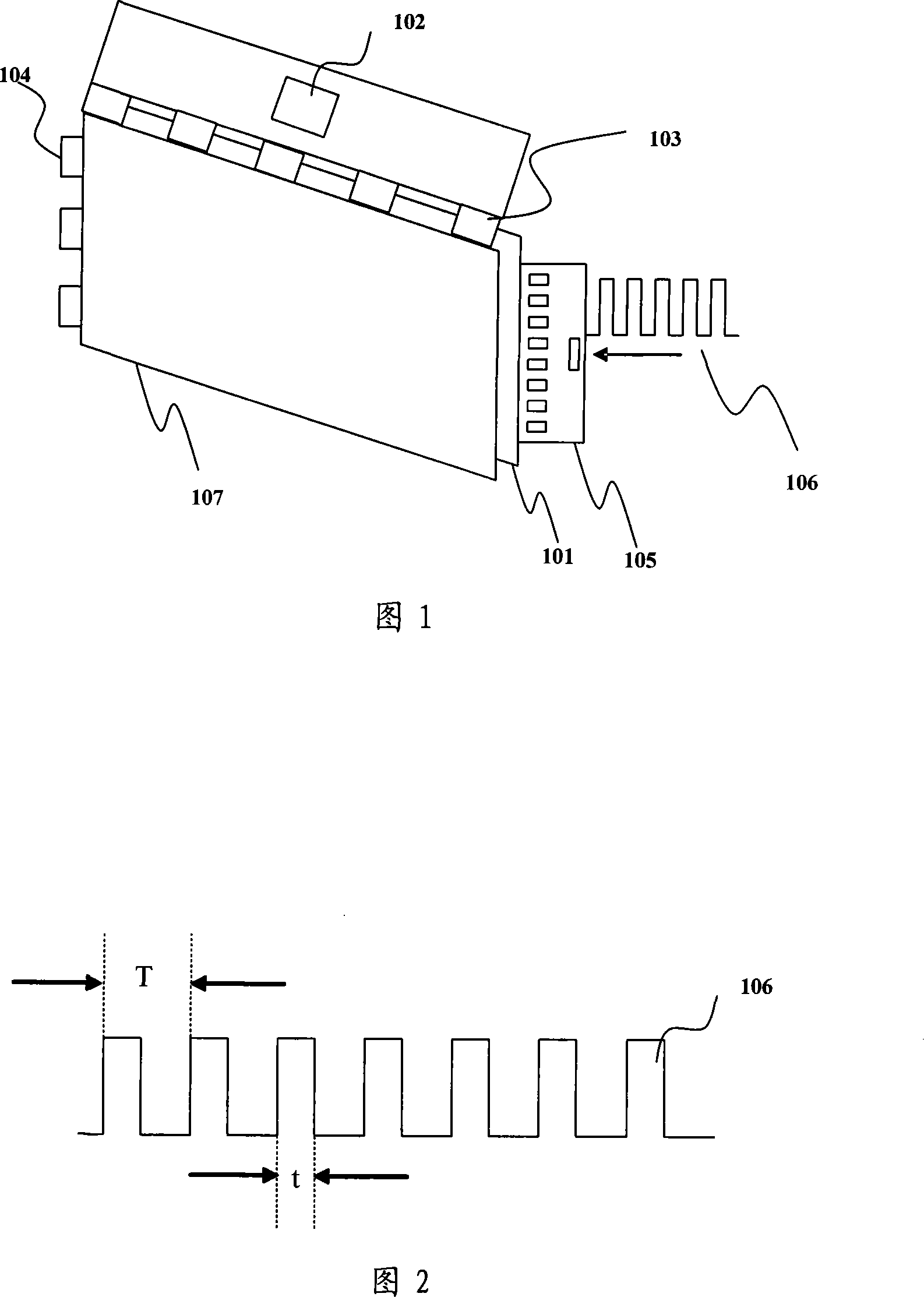
technical field [0001] The present invention relates to a method and device for improving the water mark noise of a liquid crystal display, in particular to a process for processing video signals within the level range of the pulse width modulation signal by establishing a synchronization relationship between the frame synchronization signal and the pulse width modulation signal The method is used to improve the water ripple noise of a liquid crystal display, and belongs to the field of electronic equipment manufacturing. Background technique [0002] With the continuous reduction of costs, liquid crystal displays have gradually replaced cathode ray tube (Cathode Ray Tube, hereinafter referred to as: CRT) displays in a dominant position in the market. Compared with CRT displays, liquid crystal displays have the advantages of small size, low power consumption, and low radiation. However, liquid crystal displays also have their shortcomings. The backlight source of liquid cry...

Claims


Application Information

Patent Timeline
Patent Type & Authority Patents(China)
IPC IPC(8): G09G3/36G09G3/20G02F1/133H04N5/21
Inventor 陈明
Owner K TRONICS (SUZHOU) TECH CO LTD
Learn More