Biasing arrangement, electronic apparatus, biasing method, and computer program

A technology of electronic equipment and bias device, which is applied in branch office equipment, telephone communication, electrical components, etc., and can solve problems such as echo effect

Inactive Publication Date: 2011-10-19
SONY ERICSSON MOBILE COMM AB
View PDF1 Cites 7 Cited by
  • Summary
  • Abstract
  • Description
  • Claims
  • Application Information

AI Technical Summary

Problems solved by technology

Another problem that can arise in wire connections that use a common reference for the input and output devices can be echo effects

Method used


Image

  • Biasing arrangement, electronic apparatus, biasing method, and computer program
  • Biasing arrangement, electronic apparatus, biasing method, and computer program
  • Biasing arrangement, electronic apparatus, biasing method, and computer program

Examples


Embodiment Construction

[0033] For biasing, a biasing resistor can be connected to the supply voltage and to an analog input device. The analog input device is traditionally connected to a reference voltage (eg, ground potential), such that the bias resistor and the analog input device are connected in series between the supply voltage and the reference voltage. Typically the signal output is connected to a signal on an analog input device to provide an output signal. Preferably, the signal output terminal includes a capacitor for AC coupling the output signal.

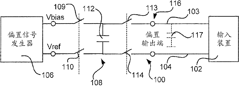
[0034] figure 1is a diagram schematically illustrating the bias device 100 according to the embodiment. The bias device 100 is suitable for use in electronic equipment connected to the input device 102 via wires 103 , 104 , for example. The biasing means comprises a bias signal generator 106 arranged to provide a bias voltage Vbias and a reference voltage Vref. The reference voltage Vref may be a ground potential or an intermediate refer...


PUM


Abstract

A biasing arrangement for an electronic apparatus having an input device connected by wires is disclosed. The biasing arrangement comprises a bias signal generator arranged to provide a bias voltage and a reference voltage; a flying capacitor circuitry having a first set of switches connected to said bias signal generator to selectively connecting and disconnecting the bias voltage and reference voltage, respectively, over a capacitor of the flying capacitor circuitry, and the flying capacitor circuitry further having a second set of switches to selectively connecting and disconnecting the voltage over the capacitor to an output of the flying capacitor circuitry, wherein the first and second sets of switches are not both in a connecting state at any time; and a wired connection between output of the flying capacitor circuitry and the input device of the apparatus. An electronic apparatus, a biasing method, and a computer program are also disclosed.

Description

technical field [0001] The present invention relates to a biasing device, an electronic device having such a biasing device, a biasing method for such an electronic device, and a computer program for realizing the biasing method. Background technique [0002] Input devices such as microphones or other devices that provide analog signals that are sensitive to introduced noise, are connected via wires, and depending on the bias voltage applied, they will face problems due to looping (for example, through multiple ground points) electromagnetic compatibility issues. In the case of a microphone, high currents to other parts of the device can cause voltage fluctuations that can be found in the microphone signal in the form of eg low frequency noise, often referred to as a "bumblebee" sound. Another problem that can arise in wire connections using a common reference for input and output devices can be echo effects. These issues must usually be addressed through a design that bal...

Claims


Application Information

Patent Timeline
Patent Type & Authority Applications(China)
IPC IPC(8): H04B15/00
CPCH04B15/00H04B15/005H04B15/02H04B2215/061H04M1/6058H04R3/00H04R3/007H04R2201/107H04R2499/11
Inventor 卡伊·乌伦彼得·克尔纳克里尔·特拉伊科夫斯基
Owner SONY ERICSSON MOBILE COMM AB
Why Eureka
Try Eureka