Explosive devices for pressurized detonation of high-pressure gases or liquids or supercritical fluids
A supercritical fluid and high-pressure gas technology, applied in blasting and other directions, can solve the problems of material damage, the size of the blast hole cannot be mastered, the explosion pressure cannot be accurately controlled, etc., to achieve the effect of reducing costs.
- Summary
- Abstract
- Description
- Claims
- Application Information
AI Technical Summary
Problems solved by technology
Method used
Image
Examples
Embodiment 1
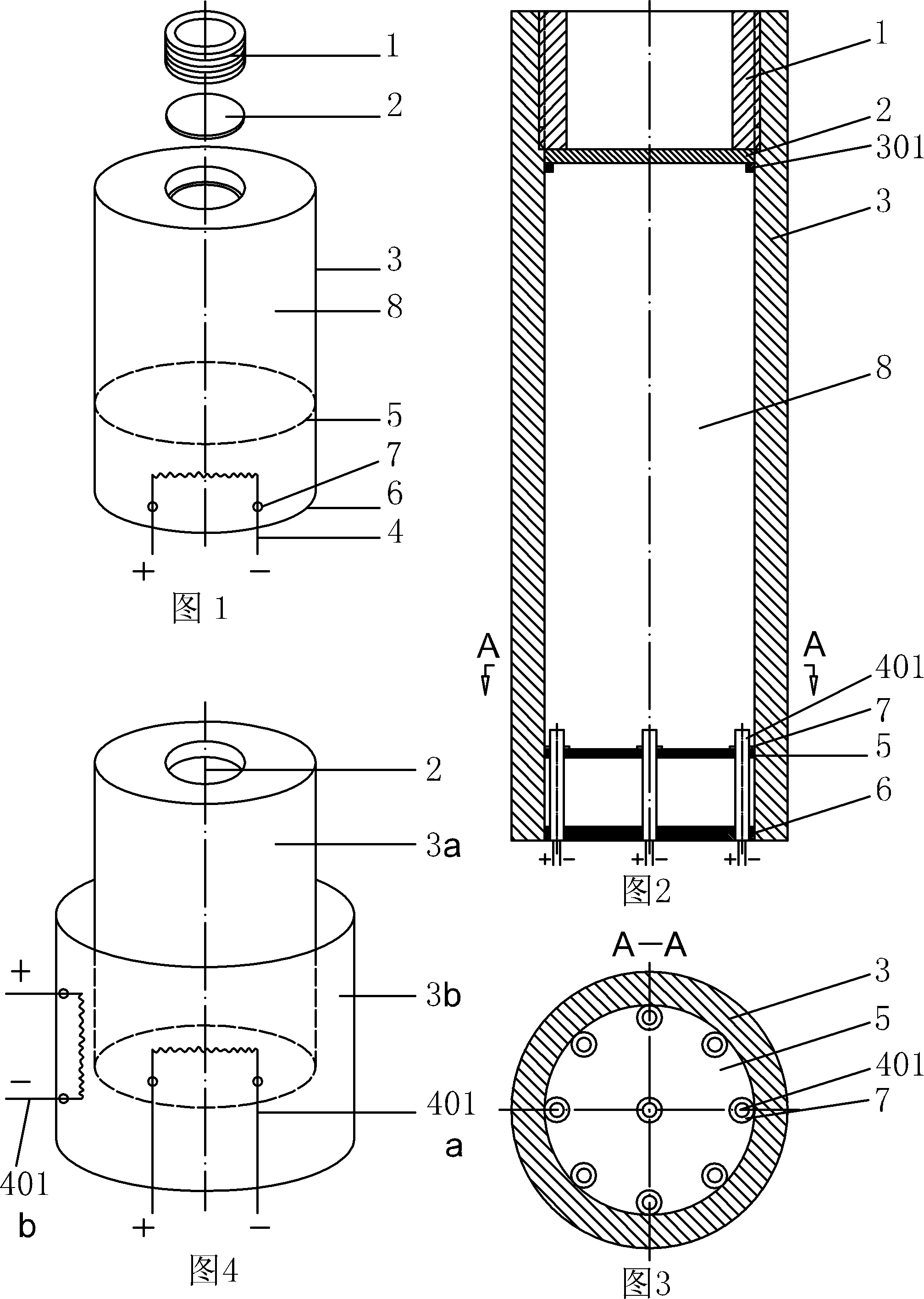
[0038] refer to figure 1 , figure 2 , image 3 As shown, the heating source body or the pressurizing body 4 selects an electric heating element 401, and at least one electric heating element 401 is embedded in the high-pressure resistant container 3 and embedded on the sealing isolation plate 5 or on the side wall, and is formed by the sealing gasket 7 Sealing, the lower part of the electric heating element 401 is set on the block 6, and the block 6 can use a block plate or an inner hexagonal sealing bolt, and the positive and negative electrodes of the electric heating element 401 adopt the existing technology explosion-proof or non-explosion-proof junction box or The junction box is placed outside the high-pressure container 3, and the sealing isolation plate 5 and the plug 6 are welded or bonded to the inner wall of the high-pressure container 3; the upper part of the high-pressure container 3 is integrally formed or welded with a circumferential boss 301 or protruding cl...
Embodiment 2
[0041] refer to Figure 4As shown, the high-pressure container 3 may be a double-layer structure, including an inner high-pressure container 3a, an outer high-pressure container 3b, an inner electric heating element 401a, and an outer electric heating element 401b built in and externally placed in the inner high-pressure resistant The container 3a and the outer high-pressure container 3b are embedded on the sealed isolation plate 5 and the side walls, and are heated internally and externally to increase the temperature rapidly. All the other structures are with embodiment 1.
Embodiment 3
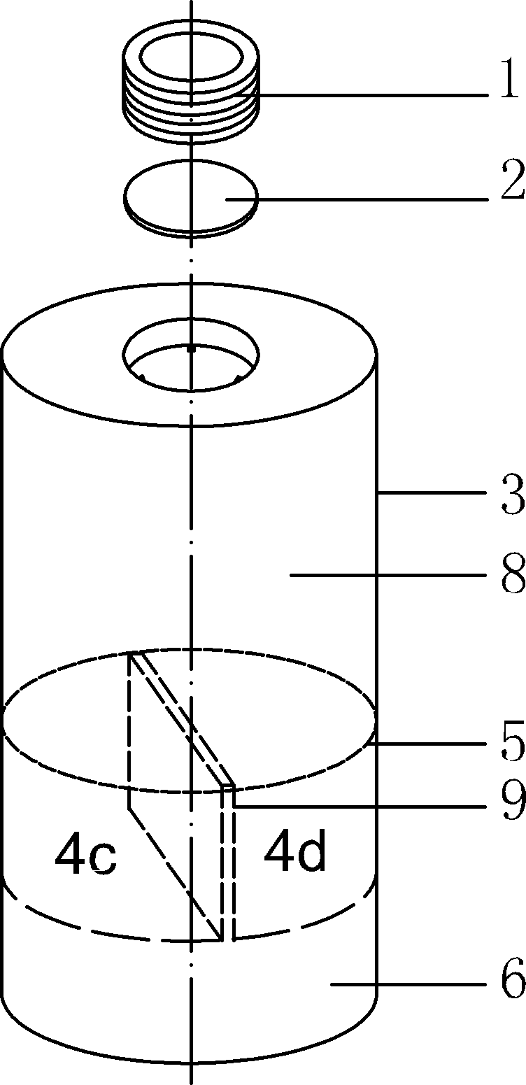
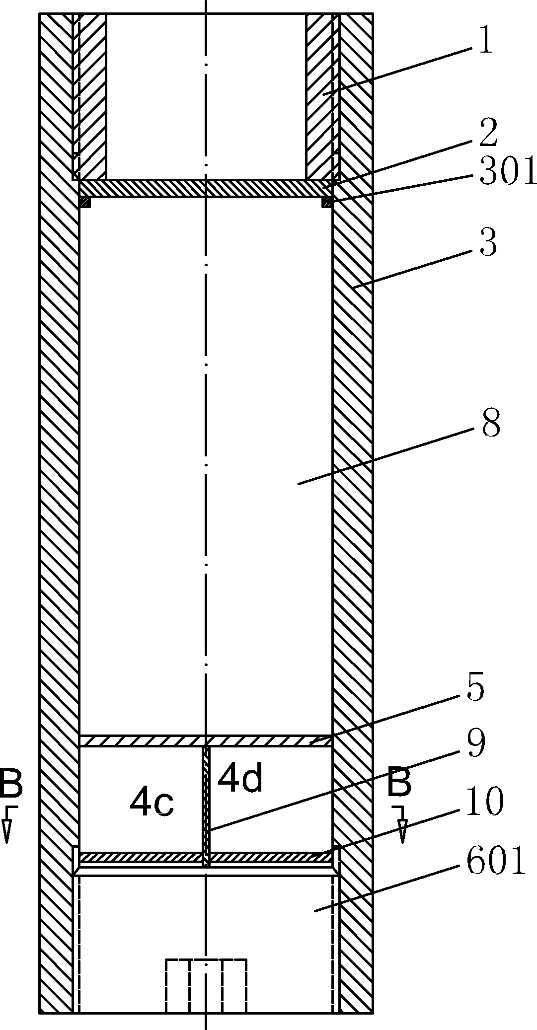
[0043] refer to Figure 5 , 6 , 7, the heating source body or pressurized body 4 is heated by chemical substance reaction, and the lower part of the high-pressure container 3 is provided with a longitudinal partition 9 and a transverse partition 10, and the transverse partition 10 is welded or bonded to the On the inner wall of the high-pressure container 3, the lower part of the longitudinal partition 9 is inserted into the through groove provided in the middle of the transverse partition 10, and is connected with the plugging 6, or connected with detachable screws. The upper part of the plate 9 is a sealed isolation plate 5; two chemical substances 4c and 4d, A and B, are arranged on the transverse partition 10, separated by the vertical partition 9. All the other structures are with embodiment 1.
[0044] When in use, different heat will be generated according to different chemical reactions. Select the appropriate chemical substance and dosage, and drive the longitudinal...
PUM
 Abstract
Description
Claims
Application Information
 - R&D
- Intellectual Property
- Life Sciences
- Materials
- Tech Scout
- Unparalleled Data Quality
- Higher Quality Content
- 60% Fewer Hallucinations
Browse by: Latest US Patents, China's latest patents, Technical Efficacy Thesaurus, Application Domain, Technology Topic, Popular Technical Reports.
© 2025 PatSnap. All rights reserved.Legal|Privacy policy|Modern Slavery Act Transparency Statement|Sitemap|About US| Contact US: help@patsnap.com


