Exhaust manifold installation structure and method for assembling and disassembling same

A technology for exhaust manifolds and installation structures, which is applied in the direction of exhaust devices, mufflers, engine components, etc., which can solve the problems of increased probability of bolt slippage, inconvenient disassembly, and delay in working hours, etc., so as to reduce the probability of bolt slippage , easy installation and disassembly, precise positioning effect

Inactive Publication Date: 2011-11-02
CHERY AUTOMOBILE CO LTD
View PDF6 Cites 9 Cited by
  • Summary
  • Abstract
  • Description
  • Claims
  • Application Information

AI Technical Summary

Problems solved by technology

[0002] At present, bolt holes are provided on the upper and lower flange surfaces of the engine exhaust manifold, and threaded holes are drilled on the corresponding positions of the exhaust flange surface of the cylinder head. The exhaust manifold is installed by means of bolt positioning. The structure will bring inconvenience to disassembly. Only by removing all the bolts can the exhaust manifold be disassembled from the engine, and the increase of bolts will increase the probability of bolt slippage. Once the bolt slips, it will cause difficulty in disassembly. Delayed working hours

Method used


Image

  • Exhaust manifold installation structure and method for assembling and disassembling same
  • Exhaust manifold installation structure and method for assembling and disassembling same
  • Exhaust manifold installation structure and method for assembling and disassembling same

Examples


Embodiment 1

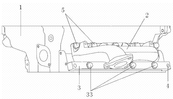
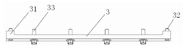
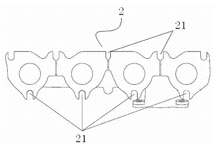
[0020] As shown in the figure, the installation structure of the exhaust manifold in this embodiment includes a cylinder head 1, an exhaust manifold 2 and a mounting bracket 3, and the flange surfaces on the upper and lower sides of the exhaust manifold 2 are provided with "U " type mounting holes 21, the cylinder head 1 is provided with bolt mounting holes at the position corresponding to the upper flange surface of the exhaust manifold, and a positioning hole is provided at the position corresponding to the lower flange surface of the exhaust manifold; the installation bracket 3 Both ends are provided with protrusions 31 facing the inner side thereof, and positioning pin holes 32 corresponding to the positioning holes are provided on the protrusions 31, and a position facing and protruding into the mounting bracket 3 is provided at the position corresponding to the "U"-shaped mounting hole. The positioning column 33 on the side is mounted on the body of the mounting bracket 3...


PUM


Abstract

The invention provides an exhaust manifold installation structure and a method for assembling and disassembling the same. The exhaust manifold installation structure comprises a cylinder cover, an exhaust manifold and an installation bracket, wherein bolt holes are formed on flange planes on the upper and lower sides of the exhaust manifold. Key points are that: bolt installation holes are formed on the cylinder cover opposite to the flange plane on one side of the exhaust manifold; positioning holes are formed on the cylinder cover opposite to the flange plane on the other side of the exhaust manifold; bolt holes on the side of the exhaust manifold, which is opposite to the positioning holes, are U-shaped installation holes; positioning pin holes are formed at the two ends of the installation bracket, which are opposite to the positioning holes; and positioning columns which face and protrude from the inner side of the installation bracket are arranged at positions which are opposite to the U-shaped installation holes. Due to the exhaust manifold installation structure, precise positioning can be ensured, the exhaust manifold installation structure is convenient to install and disassemble, installed bolts are reduced, disassembling time is saved, and the sliding probability of the bolts is reduced.

Description

technical field [0001] The invention belongs to the technical field of engine manufacturing, and more specifically, the invention relates to an exhaust manifold installation structure and its installation and disassembly methods. Background technique [0002] At present, bolt holes are provided on the upper and lower flange surfaces of the engine exhaust manifold, and threaded holes are drilled on the corresponding positions of the exhaust flange surface of the cylinder head. The exhaust manifold is installed by means of bolt positioning. The structure will bring inconvenience to disassembly. Only by removing all the bolts can the exhaust manifold be disassembled from the engine, and the increase of bolts will increase the probability of bolt slippage. Once the bolt slips, it will cause difficulty in disassembly. Delayed working hours. Contents of the invention [0003] The object of the present invention is to propose a convenient installation and disassembly exhaust man...

Claims


Application Information

Patent Timeline
Patent Type & Authority Applications(China)
IPC IPC(8): F01N13/10F01N13/18
Inventor 刘和义张侠
Owner CHERY AUTOMOBILE CO LTD
Why Eureka
Try Eureka